ARMY TM 5-6115-633-14&P
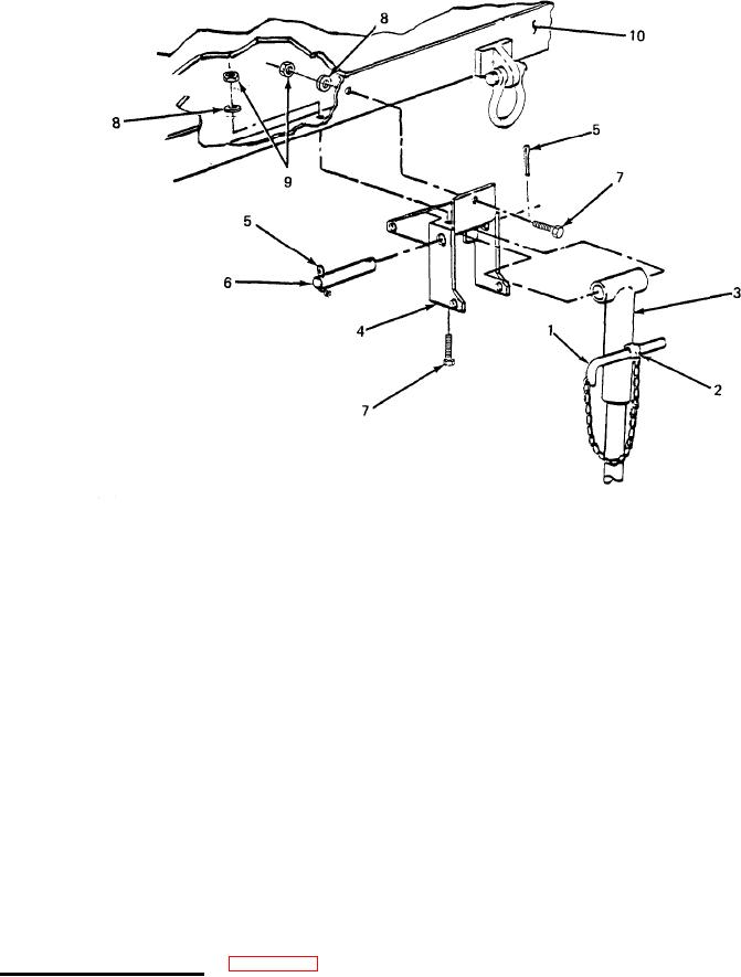
Figure 5-1. Leg Prop Assembly Replacement.
(2) Installation.
Position bracket (4) on trailer frame (10) and install three screws (7), three flat
(a)
washers (8), and three nuts (9). Tighten hardware to secure bracket.
Lift leg assembly into bracket (4) and secure by inserting angled bar(1) through
(b)
holes in bracket and boss (2) on upper leg (3).
Position leg assembly to line up boss (2) on top of leg with pivot holes in bracket
(c)
(4). Insert pivot shaft (6).
Insert cotter pin (5) in pivot shaft (6) and bend cotter pin legs in opposite directions.
(d)
Pull out angled bar (1) to unlock leg prop assembly.
(e)
(f)
Swing leg prop assembly up into traveling position and secure by inserting angled bar
(1) through holes in bracket (4) and boss (2) on upper leg (3).
b. Leg Prop Assembly Repair. (See figure 5-2.) Repair of the leg prop assembly is limited to
welding and repainting. However, partial disassembly is possible to facilitate repair. If required,
repaint in accordance with MIL-T-704, Type F, color Green No. 383 of MIL-C-46168.
5-2

