TM5-6115-593-34
NAVFAC P-8-631-34
TO-35C2-3-463-2
Section IV. VOLTAGE REGULATOR
4-17. GENERAL. The voltage regulator assembly
consists of the voltage regulator mounted with the
electromagnetic interference (EMI) filter pack as a
complete unit. The voltage regulator assembly senses
generator voltage, compares the voltage with a
reference voltage, and supplies field (stator) current to
the generator to maintain voltage regulation. The EMI
filter pack, associated with the voltage regulator,
provides EMI suppression. The voltage regulator
assembly is a separate unit mounted in the AC-DC
control box assembly.
4-18. INSPECTION. Remove cover to facilitate
inspection. Check voltage regulator wire connections on
the terminal board. Check grounding straps for
looseness. Check all components for loose mounting,
poor connections, broken wires, or any other signs of
damage.
4-19. TEST. The voltage regulator is tested to
determine operational capability, as follows (see figures
4-7 and 4-8).
a.
Operational Test.
(1)
Connect voltage regulator as shown in
test setup, figure 4-7.
(2)
Disconnect leads from transformer T1
primary, and connect to the 120 volt
input tap.
(3)
Mark position of potentiometer R4 on
voltage regulator.
NOTE
R1 in test setup substitutes for the
motor-operated potentiometer in the
AC-DC control box assembly. This
adjustment is provided to control the
generator voltage. When adjusted to
its
maximum
resistance
position
(CCW), minimum generator voltage is
obtained. Maximum generator voltage
is obtained with minimum resistance
(cw).
(4)
Set potentiometer R4 on voltage
regulator fully counterclockwise.
(5)
Adjust potentiometer R1 (in figure 4-
7), for maximum resistance.
(6)
Slowly adjust R1 toward minimum
resistance. Before reaching minimum
resistance, light bulb should come on
to near full
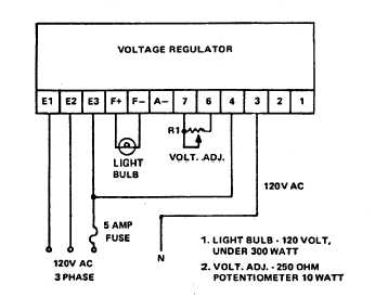
Figure 4-7. Voltage Regulator, Test Setup
4-14