TM5-6115-593-34
NAVFAC P-8-631-34
TO-35C2-3-463-2
LEGEND FOR FIGURE 13-21
1.
Barrel assy
11.
Seal
21.
Screw
31.
Plunger
41.
Screw
2.
Screw
12.
Connector
22.
Dowel
32.
Bearing
42.
Stop
3.
Plate
13.
Screen
23.
Bushing
33.
Shim
43.
Shaft
4.
Gasket
14.
Plug
24.
Carrier assy
34.
Plunger
44.
Adj.screw
5.
Ring
15.
Adj. nut
25.
Spring
35.
Barrel
45.
Seal
6.
Seal
16.
Seal
26.
Shim
36.
Housing
46.
Seal
7.
Seal
17.
Valve
27.
Plunger
37.
Screw
47.
Ring
8.
Plug
18.
Nut
28.
Plunger assy
38.
Cover
48.
Ball
9.
Cap
19.
Nut
29.
Driver
39.
Ball
49.
Body
10.
Spring
20.
Plug
30.
Spacer
40.
Throttle shaft assy
top of the pump. Reinstall plug.
(5) Connect line to fuel pump shut-off valve.
(6) Connect a No. 4 hose to the cooling bleed
check valve on the gear pump. Drain into
splash tray under pump.
CAUTION
Never operate gear pump with the
drain plugged.
(7) Never remove fuel pump damper either during
testing or operation as it will cause erratic pump
performance and accelerate wear.
(8) Completely open the fuel pump shut-off valve
by turning knob clockwise (12, figure 13-22),
and the flow control valve.
(9) Open throttle to wide open position (secure
open with a spring), and start and run pump at
500 rpm.
(10)
If pump is newly rebuild or has been
opened, run at slightly over rated speed for 5
minutes to flush,
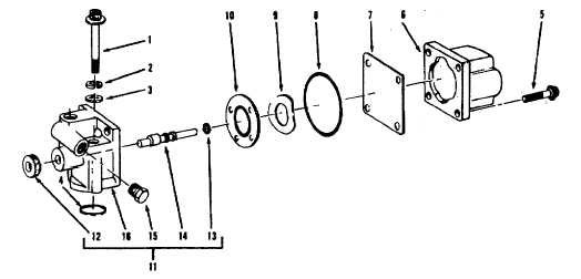
LEGEND
1.
Screw
5.
Screw
9.
Washer
13.
O-ring
2.
Lockwasher
6.
Coil
10.
Valve
14.
Shaft
3.
Washer
7.
Shield
11.
Housing
15.
Plug
4.
O-ring
8.
O-ring
12.
Knob
16.
Housing
Figure 13-22. Fuel Shut-off Valve, Exploded View
13-40