TM5-6115-593-34
NAVFAC P-8-631-34
TO-35C2-3-463-2
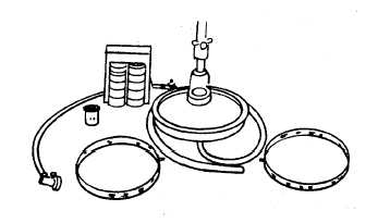
Figure 13-18. Spray Angle Tester
(2) Attach drain hose to spray angle tester base
and place loose end in injector test stand
drain pan.
(3) Assemble cup seat spacer H-10 to seat
bracket bore.
(4) Place H-2 seat in seat spacer and bracket
bore.
(5) Place target ring in base of spray angle
tester.
i.
Installation,
Assembly,
and
Operating
Instructions for the Injector Test Stand . The
injector test stand must be located near hot and cold
water connections. Water temperature, controlled by
a mixing valve, is used to maintain test oil at a 90 to
95°F (32 to 35°) temperature range. If temperature
exceeds 135°F 57°C) drain and replace with new
test oil. (See figure 13-19.)
(1) Fill test oil tank 3/4 full of test oil and
maintain this level or higher during test. Test oil
capacity is approximately 5 gallons. It is available
as Part No.99011-68.
(2) Fill the hydraulic fluid reservoir to half level
in sight bulb with clean Type A automatic
transmission fluid. Be careful not to allow
oil to enter the standpipe in center of
reservoir.
(3) Fill cambox with SAE 30 non detergent
lubricating oil to top of sight glass. Refill
when oil level gets low in sight glass.
(4) Plug electrical connection into receptacle
carrying the necessary voltage to operate
the test stand.
(5) A motor driven shaft and cam are housed in
the cambox. The cam actuates the vertical
push rod at the bottom of the housing.
(6) The push rod is connected to the injector by
a link so the injector plunger will be actuated
by cam action just as it is in the engine.
(7) Injectors are clamped in the test stand by
hydraulic pressure from the cylinder, piston
rod, and injector seat. The injector seat
contains a removable orifice to restrict the
metered fuel flow and cause a back
pressure simulating compression pressures
as found in the engine.
(8) Before clamping the injector in the test
stand, the cam must be timed by rotating
the timing wheel so the wheel mark and
pointer are aligned.
(9) Shop air pressure regulated by air regulator
is used to apply a balanced force on the
hydraulic system. The air gauge at top of
hydraulic reservoir is used as a reference
indicating that pressure has not changed.
(10)
When the air valve is opened, air
travels up the pipe in the center of the tube
type hydraulic reservoir and exerts a
downward pressure against the column of
hydraulic fluid.
(11)
When both the air valve and the
hydraulic valve are opened, hydraulic fluid
is admitted under the piston in the cylinder
and lifts the injector into clamped
13-36