TM5-6115-593-34
NAVFAC P-8-631-34
TO-35C2-3-463-2
Figure 11-17. Drive Plate Assembly
and attach with screws (57) and locking plates
(58). After tightening, turn tabs up on locking
plates to lock bolts in place.
(b)
Push drive plate assembly (with coupling hub
attached) toward engine flywheel. Align holes
and install bolts. Tighten and torque to 112
footpounds (157 joules) when dry. (See figure 11-
18.)
(c)
Tighten setscrew (60) on coupling hub (61).
Figure 11-18. Drive Plate Assembly and Engine
Flywheel Housing
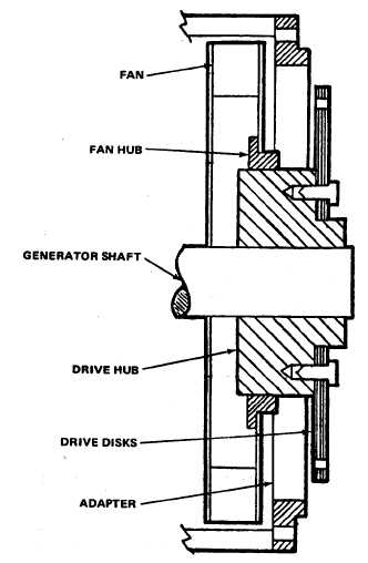
11-11. FAN. The internal fan draws cool air through the
cover at the exciter end of the generator, and exhausts
warm air through the screen over the adapter assembly.
The fan is key mounted directly to the drive plate
assembly coupling hub.
a.
Replacement. Remove and replace fan as
follows:
(1)
Removal. Refer to figure 11-3. To remove
the fan, the drive plate assembly must be removed.
Refer to paragraph 11-10.
(a)
With covers and drive plate
assembly removed, remove adapter (70) by removing
bolts securing adapter to engine flywheel housing and
screws (68) and washers (69) securing adapter to
generator frame.
(b)
Remove generator mounting
bolts, and with crane, move
11-28