TM5-6115-593-34
NAVFAC P-8-631-34
TO-35C2-3-463-2
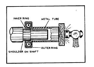
temperature of from 220 to 250F (103 to 121°C) in a
clean thermostatically controlled oven. Start the heated
bearing into the shaft. Then use a fiber or soft metal tube
to tap bearing into place. (See figure 11-16.) Make
certain that pressure is applied only to the bearing inner
ring.
Figure 11-16. Install Bearing on Generator Shaft
(b) Press bearing onto shaft until inner ring is
against bearing shoulder on the shaft.
Continue assembly after
the bearing has cooled.
(c) Using a crane, install endbell (85) and PMG
stator and exciter assembly, over generator
shaft.
(d)
Install screw (80) and washers (81).
(e) Install screws and lockwashers (82 and 83)
attaching bearing cap (84) to endbell (85).
(f)
Line up lockwasher (87) and tighten nut (86)
to secure bearing.
(g) Tighten setscrew (52) in exciter rotor (38).
(h)
Install PMG rotor (37) with pin (36), scres
(35), and washer (34).
(i)
Replace cover (30) with screws (26 and 28),
washers (29), and nuts (27).
11-10. DRIVE PLATE ASSEMBLY.
a.
General. The generator shaft is directly
driven by the engine shaft through the drive
plate assembly, figure 11-17. The coupling
compensates for misalignment between the
two shafts to eliminate injurious stress on
the connection components.
b.
Replacement.
(1)
Removal. Remove drive plate
assembly (59, figure 11-3) as follows:
(a)
Remove cover (63) and cover (67)
by removing screws (64), washer
(66), and nut (65).
(b)
Remove screws attaching drive
plate assembly to engine flywheel.
(See figure 11-18.)
(c)
Loosen setscrew (60) in coupling
hub (61).
(d)
Push drive plate assembly as far as
possible towards the generator fan,
in order to gain access to the hub
screws (57).
(e)
Remove screws (57) by
straightening locking plate (58).
Remove drive plate assembly.
(2)
Replacement. Install drive plate assembly
as follows:
(a)
Locate drive plate assembly onto hub (61)
11-27