TM5-6115-585-34
NAVFACP-8-623-34
TO-35C2-455-2
TM-05684C/05685B-34
(3) Testing Field Coils. See Operator and
Organizational Maintenance Manual.
(4) Testing Brushes.
See Operator and
Organizational Maintenance Manual.
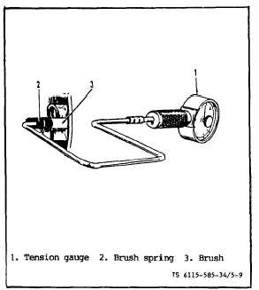
(5) Testing Brush Springs. Style I Starter.
(see figure 5-9).
Measure brush spring with tension meter. Push the
brush and take reading just as the brush projects
a little from the brush holder. On a new brush,
the spring tension should be 32 to 40 ounces. If
brush spring tension is below 20 ounces, replace
it.
Figure 5-9. Testing Brush Spring Tension
STYLE I Starter Only.
(6) Testing Brush Springs. Style II Starter.
Firmly hold brush holder and push the brush
against the brush spring until completely inside
of its guide. If little or no resistance (tension)
is present, spring should be replaced. Badly worn
or pitted brush surface may indicate weak spring.
(7) Testing Solenoid Switch. Style I Starter.
(see figure 5-10).
(a) Check to be sure plunger moves
freely in coil. Measure pull-in coil current using
a ammeter. See Test A, figure 5-10, Current should
not exceed 16 amps.
(b) Measure the hold-in current using
Test B, figure 5-10. Current should not exceed
amps.
(c) Check total hold and pull current
draw using Test C, figure 5-10. Total current
6
should not exceed 25 amps. Replace defective sole-
noid switch.
(8) Testing Solenoid Switch. Style II Starter.
(see figure 5-10).
(a) With solenoid on starter, push the
solenoid plunger in and release it. The plunger
should return to its original position. Plunger
should slide in and out freely when push by hand.
(b) Check for continuity between terminal
“B" and terminal “M” with an ohmmeter. There
should be no continuity.
(c) Push the plunger in and hold while
checking continuity between termiml “B” and “M”.
The ohmmeter should read zero ohm with complete
continuity. If no continuity reading, the solenoid
is defective, replace it.
g. Repair
(1) Repairing Starter. Repair starter by
replacing defective components. Repair procedures
for individual components are as follows:
(2) Repairing Armature. If the commutator
wear or runout is not excessive, (max 0.004), it
may be resurfaced as follows:
(a) Resurfacing Commutator. Place the
armature in a lathe.
Style I starters may be
turn down with a cutting tool. Style II starters
my Not be turn down with a cutting tool! Only
00 or 000 sandpaper may be used on Style II and
if wear or runout cannot be corrected, the Style
II armture must be replaced! The Style I
commutator turn down may not reduce the diameter
of commutator below 1-1/16 inches.
(b) Undercutting Mica. After cummutator
is resurfaced, undercut mica to a depth of 0.025
to 0.032 inch using a power driven undercutting
tool.
If no power driven tool is available, the
mica may be under cut by hand. See figure
5-11.
NOTE
Use care in undercutting.Do not widen
commutator slots by removing metal from
bars, and do not leave a thin edge of mica
next to bars. Figure 5-11 illustrates good
and bad exa of undercutting. After
mica has been undercut, polish commutator
in a lathe with number 00 to 000 sandpaper
while the armature is rotating. Remove all
copper sand and mica with compressed air.
Change 8
5-7