TM5-6115-585-34
NAVFAC P-8-623-34
TO-35C2-455-2
TM-05684C/05685B-34
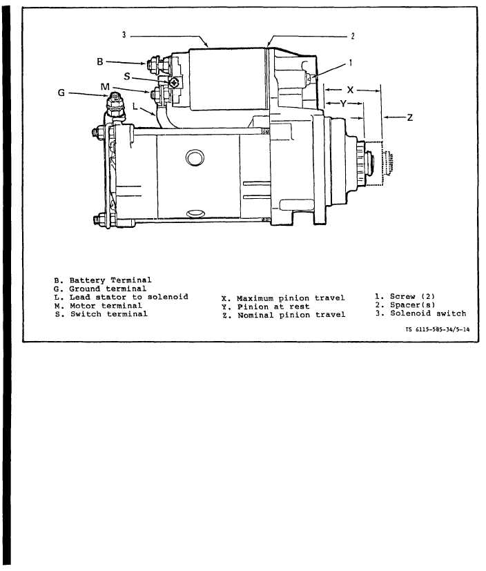
Figure 5-14. Checking Pinion Travel STYLE II Starter
(e) If adjustment of pinion gear travel
L. Installation.
Refer to Operator and
is required, remove screws (1) lift off solenoid
Organization Maintenance Manual:
(3). Adjust pinion travel by adding or removing
mounting spacers (2). Increasing the number of
washers will decrease maximum travel distance;
and removing washers will increase maximum travel
distance.
NOTE
Solenoid mounting scerw removal may requ-
ire the use of a impact type driver.
(f) Reinstall the solenoid (3) make sure
plunger engages the lever. Position the spacers
(2) and install new screw (1) if necessary.
(g) Repeat steps (a) thru (e) until pinion
travel is acceptable.
(h). Remove power source and install lead
(L) on terminal (M). secure with nut and washer.
5-12
Change 8

