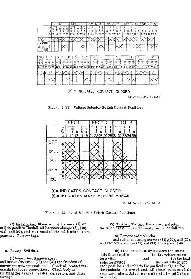
Figure 4-17.
Figure 4-18.
(2) Installation. Place wiring harness (7) or
(94) in position, install all harness clamps (5), (12),
(92), and (93), and reconnect electrical leads to com-
ponents.
Remove tags.
4 - 4 4 . L o a d B a n k C o n t r o l P a n e l A s s e m b l y .
a.
R~tary
Switches.
(1) Inspection. Remove cover
( 9 ,
f i g .
4 - 1 4 )
and insr)ect switches (23) and (36) for freedom of
.,
movement between positions.
minals for loose connections.
switches for cracks, breaks,
damage,
‘ Check all contact ter-
Check body of
corrosion, and other
(2) Testing. To test the rotary selector
switches use a multimeter and proceed as follows:
(a) Remove switch knobs
( 1 8
a n d
2 5 ,
f i g .
4 - 1 4 ) and switch mounting screws (21), (30), and (32),
and remove switches (23) and (36) from panel (56).
(b) Test for continuity between the termi-
nals illustrated in f i g u r e 4 - 1 7 for the voltage selec-
tor switch ( 3 6 , f i g . 4 - 1 4 ) and f i g u r e 4 - 1 8 for the load
selector switch ( 2 3 , f i g . 4 - 1 4 ) . Sequentially select
each position and refer to the particular figure for
the contacts that are closed. All closed circuits shall
read zero ohms. All open circuits shall read 5 ohms
to infinity.
C h a n g e 4
4 - 4 1