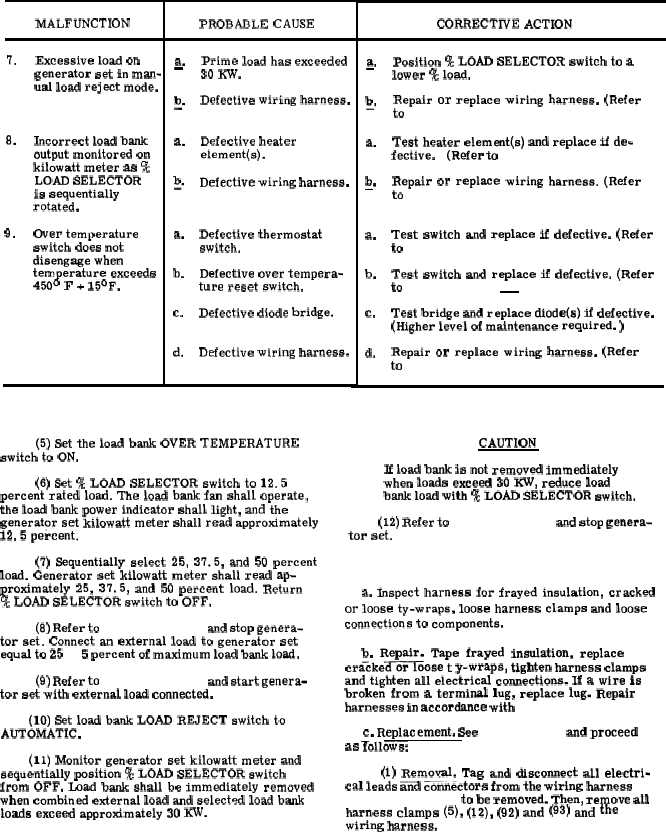
MALFUNCTION
7.
8,
9.
Excessive load on
generator set in man-
ual load reject mode.
Incorrect load bank
output monitored on
kilowatt meter as %
LOAD SELECTOR
is sequentially
rotated.
Over temperature
switch does not
disengage when
temperature exceeds
450° F + 15°F.
Table 4-8. Load Bank Troubleshooting (Cont)
CORRECTIVE ACTION
PROBABLE CAUSE
a.
Prime load has exceeded
—
30 Kw.
b
Defective wiring harness.
-“
a.
Defective heater
element(s).
b
Defective wiring harness.
-“
a.
Defective thermostat
switch.
b.
Defective over tempera-
ture reset switch.
c.
Defective diode bridge.
d,
Defective wiring harness.
(5) Set the load bank OVER TEMPERATURE
switch to ON.
(6) Set % LOAD SELECTOR switch to 12.5
percent rated load. The load bank fan shall operate,
the load bank power indicator shall light, and the
generator set kilowatt meter shall read approximately
12.5 percent.
(7) Sequentially select 25, 37.5, and 50 percent
load. Generator set kilowatt meter shall read ap-
proximately 25, 37.5, and 50 percent load. Return
% LOAD SELECTOR switch to OFF.
(8) Refer to paragraph 2-13 and stop genera-
tor set. Connect an external load to generator set
equal to 25 ± 5 percent of maximum Ioad bank load.
(9) Refer to paragraph 2-12 and start genera-
tor set with external load connected.
(10) Set load bank LOAD REJECT switch to
AUTOMATIC.
(11) Monitor generator set kilowatt meter and
sequentially position % LOAD SELECTOR switch
from OFF. Load bank shall be immediately removed
when combined external load and selected load bank
loads exceed approximately 30 KW.
4-38
a.
—
b-“
a.
b-“
a.
b.
c.
d.
Position ‘% LOAD SELECTOR switch to a
lower % load.
Repair or replace wiring harness. (Refer
to paragraph 4-43.)
Test heater element(s) and replace if de-
fective.
(Refer to paragraph 4-48.)
Repair or replace wiring harness. (Refer
to paragraph 4-43.)
Test switch and replace if defective. (Refer
to paragraph 4-47.)
Test switch and replace if defective. (Refer
to paragraph 4-44 d .)
Test bridge and replace diode(s) if defective.
(Higher level of maintenance required. )
Repair or replace wiring harness. (Refer
to paragraph 4-43.)
CAUTION
If load bank is not removed immediately
when loads exceed 30 KW, reduce load
bank load with ‘% LOAD SELECTOR switch.
(12) Refer to paragraph 2-13 and stop genera-
tor set.
4-43. Wiring Harness. (Figure 4-16)
a. Inspect harness for frayed insulation, cracked
or loose ty-wraps, loose harness clamps and loose
connections to components.
b. Repair. Tape frayed insulation, replace
cra%ke=oose t y-wraps, tighten harness clamps
and tighten all electrical connections. If a wire is
broken from a terminal lug, replace lug. Repair
harnesses in accordance with para 3-139.
C. Replacement. See f i g u r e 4 - 1 4 and proceed
as Tolloww.
(1) Removal. Tag and disconnect all electri-
cal leads and connectors from the wiring harness (7
or 94, fig. 4-14) to be removed. The% remove all
harness clamps (5), (12), (92) and (93) and the
wiring harness.