T M 5 - 6 1 1 5 - 5 4 5 - 1 2
T O - 3 5 C 2 - 3 - 4 4 4 - 1
N A V F A C P - 8 - 6 2 6 - 1 2
T M - 0 0 0 3 8 G - 1 2
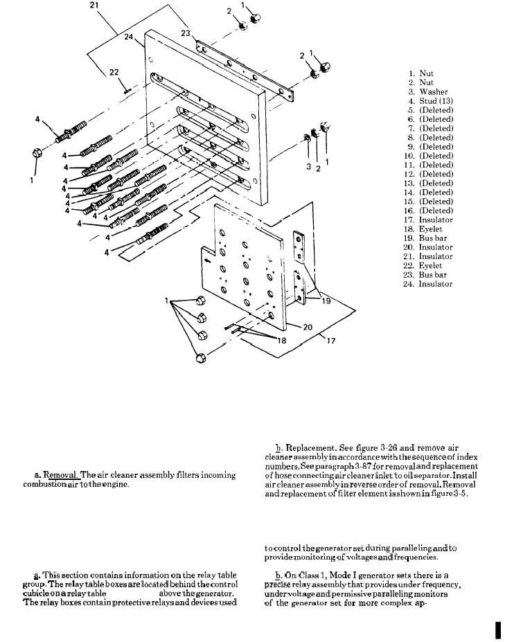
F i g u r e 3 - 2 5 .
R e c o n n e c t i o n B o a r d
S E C T I O N X X . A I R C L E A N E R A S S E M B L Y
3 - 1 4 7 . A i r C l e a n e r A s s e m b l y.
~. Replacement. See figure 3-26 and remove air
cleaner assembly in accordance with the sequence of index
numbers. See paragraph 3-87 for removal and replacement
a. Removal. The air cleaner assembly filters incoming
of hose connecting air cleaner inlet to oil separator, Install
combustion air to the engine.
air cleaner assembly in reverse order of removal. Removal
and replacement of filter element is shown in figure 3-5.
S E C T I O N X X I . R E L A Y T A B L E G R O U P
3 - 1 4 8 . G e n e r a l .
to control the generator set during paralleling and to
provide monitoring of voltages and frequencies.
a. This section contains information on the relay table
~: On Class 1, Mode I generator sets there is a
grofip. The relay table boxes are located behind the control
precw.e relay assembly that provides under frequency,
cubicle on a relay table (19, Fig 3-24) above the generator.
under voltage and permissive paralleling monitors
The relay boxes contain protective relays and devices used
of the generator set for more complex ap-
C h a n g e
1
5
3 - 7 2 . 3
/ ( 3 - 7 2 . 4
b l a n k )