TM 5-6115-46-534
T0 35C2-3-446-2
NAVFAC P-8-625-34
TM 06858B/06859D-34
(a) Connect the load and instrumentation
correct, serious damage or injury could be done to
in accordance with the applicable figure of MIL-HDBK-
connected equipment and to personnel as a result of
705, Method 205.1, paragraph 205.1.10 for one volt-
reversed motor rotation or excessive current
age and frequency.
surges.
(b) Install appropriate thermocouples to
b. Apparatus. A phase sequence (rotation) in-
measure the following temperatures:
dicator as described and illustrated in MIL-HDBK-
705, Method 116.1 or a three-phase motor whose
1. Engine coolant (engine outlet ad inlet)
direction of operation in relation to phase sequence
2. Exhaust gas(es) (the exhaust manifold(s
is known shall be required.
shall be drilled and tapped as close as
possible to the combustion chamber(s).
c.
Procedure.
3. Lubricating oil sump.
4. Engine comtnistion air in (located at
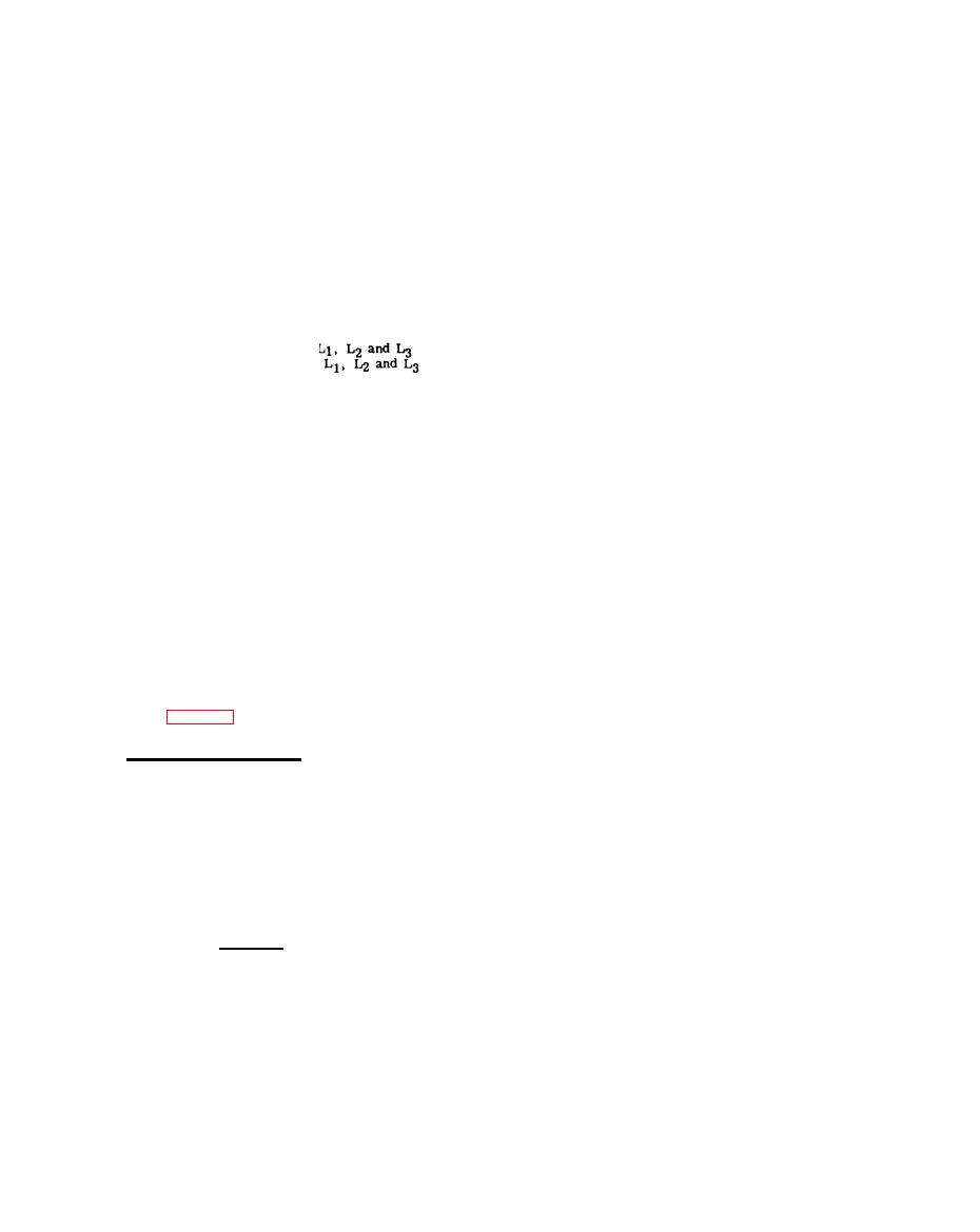
(1) Connect the generator set load terminals
the inlet of the intake manifold).
to the applicable test applicable test apparatus for
one of the set three-phase voltage connections. Re-
(c) Install appropriate pressure instrumen-
check the connections to insure that
tation to measure the following items:
of the generator set are connected to
of the test apparatus respectively.
1. Exhaust pressure (combined exhaust
gases in exhaust manifold).
(2) Start and operate the generator set at rated
voltage and frequency. The set indicating instruments
2. Intake air manifold pressure (between
shall be sufficient indication of output voltage and
air filters and manifold).
frequency.
(d) Obtain and record the barometric and
(3) Close the circuit interrupter and determine
water vapor pressures (see MIL-HDBK-705, Method
the direction of phase sequence (rotation) by observ-
220. 2).
ing the indicator, or by noting the direction of rota-
tion if a three-phase motor is used. Record results.
(e) Bypass the set circuit interrupter.
(4) Check the phase sequence (rotation) of the
(f) Connect the set to a source of fuel con-
power output of each power receptacle on the genera-
taining a specified fuel required by the procurement
tor set by connecting the applicable test apparatus to
the receptacle and repeating steps (1) thru (3) above.
document.
(2) Test.
(5) Repeat steps (a) thru (d) above for all other
three-phase voltage output connections of the genera-
tor set.
(a) Start and operate the generator set and
allow it to stabilize at rated load, rated voltage and
d. Results. The phase sequence (rotation) as
rated frequency (speed). During this period, readings
indicated by the test shall be checked against the re-
of all instruments including thermal instrumentation
quirements of table 7-1.
shall be recorded at minimum intervals of 10 minutes.
If necessary, adjustments to the load, voltage and
7-24.
MAXIMUM POWER TEST.
rated frequency. However, adjustments to the volt-
age and frequency shall be limited to those adjustments
a. General. The maximum power of a genera-
available to the operator, specifically adjustments to
tor set is a function of the ambient conditions (tem-
the voltage or frequency adjust devices. On generator
perature and altitude) and the mechanical condition
sets utilizing a droop-type speed control system as
of the engine at any particular time.
the prime speed control, the speed and droop portions
of the control may be adjusted. No other adjustmetis
b. Apparatus. Instrumentation for measuring
to the voltage and frequency control systems shall be
load conditions, field voltage and current, pressures
made. Adjustments to the load, voltage or frequency
and temperatures shall be as described and illustrat-
controls shall be recorded on both the data sheet and
ed in MIL-HDBK-705.
recording chart(s). Stabilization Will be considered to
have occurred when four consecutive voltage and curr-
ent recordings of the exciter field either remain un-
CAUTION
changed or have only minor variations about an equili-
brium condition with no evident continued increase or
This procedure subjects the generator set
decrease in value after the last adjustment to the load,
to a severe overload which may be dam-
voltage or frequency has beeq made.
aging if maintained for too long a period of
time.
(b) Perform this test using resistive load
only. Remove reactive load after stabilizaticm.
(1) Preparation for test.
7-16


