TM 5-6115-465-34
NAVFAC P-8-625-34
TO 35 C2-3-446-2
TM06858B/06859D-34
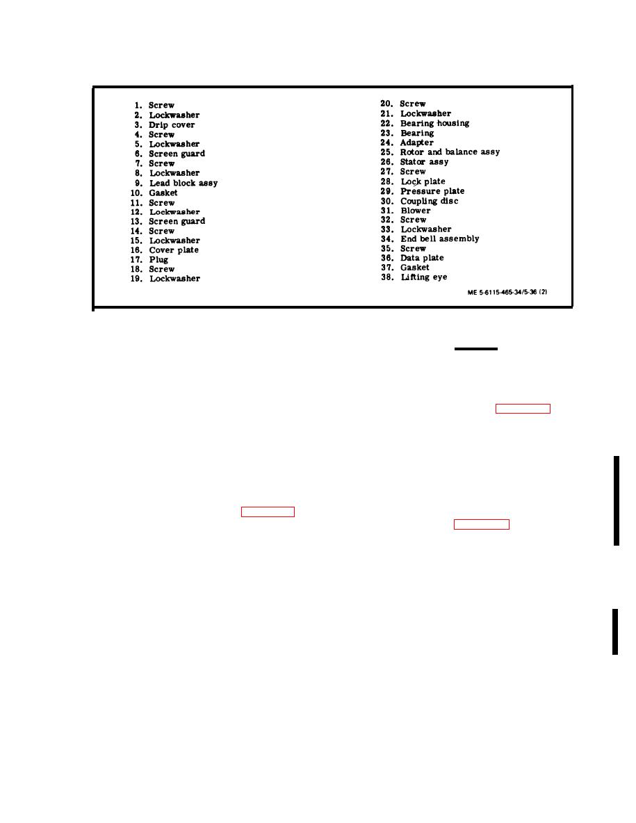
Generator Assembly, Exploded View (Sheet 2 of 2)
Figure 5-36.
(9) Thread five turns of screw (18) into rotor
CAUTION
shaft and, using a suitable puller, remove bearing
(23).
Use extreme care when lifting rotor and
balance assembly from the stator assem-
(10) Support bearing on the head of a suitable
bly.
press and press out adapter (24).
(22) Using a suitable lifting device, remove
(11) Remove the lifting eye bolt from the gen-
rotor and balance assembly (25, figure 5-36) from
erator stator.
stator assembly (26) and position on a support.
(12) Cut a sufficient length of 1/2 inch bar
(23) Remove lifting eye bolt and steel bar.
stock steel to fit across the diameter of the coupling
disc end of the generator assembly.
NOTE
(13) Center punch and drill a l-inch hole
If the alternator assembly is to be sent to a
through the center of the bar stock.
higher level, the rotor assembly must be
secured in the stator assembly to prevent
(14) Secure the bar stock to the rotor assem-
bly using the generator lifting eye (see figure 5-37).
damage while in transit. The bar stock
steel illustrated in figure 5-37 can be used
(15) Locate and center punch a hole at each
for this purpose.
end of the bar stock in line with the generator housing
mounting holes.
NOTE
(16) Remove the generator lifting eye and the
If a steel bar is not available, carefully
steel bar.
stand generator on end and remove rotor.
(17) Drill a 5/8 inch hole at each center
punched position.
(24) Remove screw (27) to remove plate (28),
(18) Secure the steel bar to the stator (gen-
pressure plate (29), coupling disc (30), blower wheel
erator housing) with two of the screws used to secure
(31) from rotor and balance assembly (25).
the generator to the engine flywheel housing.
(19) Install the generator lifting eye bolt.
(25) Remove screws (32) and lockwashers (33)
(20) Using a suitable lifting device, lift the
to remove end bell assembly (34) from stat or (26).
generator by the eye bolt and stand it on its end bell
NOTE
NOTE
Feed leads to stator through end be 11 as it
Use block as necessary to hold the genera-
is removed.
tor in the upright position.
(21) Remove the two screws securing the steel
bar to the stator.
3
5-57
Change


