T.O. 35C2-3-442-2
P-9-TM-457-35
TM 5-6115-457-34
TM-07464A-35
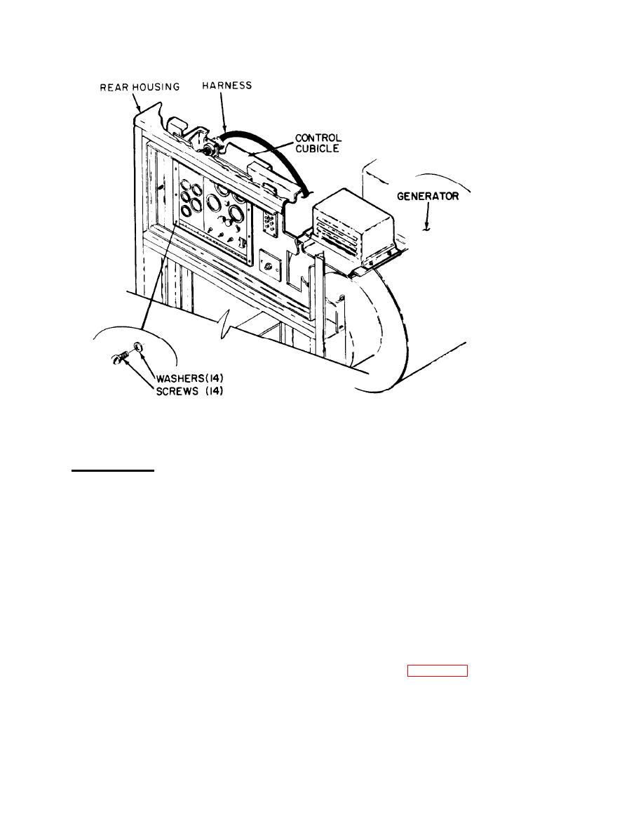
Figure 2-2. Control cubicle, removal and installation
circuit breaker, control cubicle, conven-
2-7.
GENERATOR.
ience receptacle, exciter regulator,
mode I or mode II relay box, load meas-
a. Removal. Remove generator as
urement unit, tactical relay box, pre-
follows:
cise relay box (on 50/60 hertz precise
generator sets), and kit control boxes,
1. Refer to Operator and Organiza-
if installed.
tional Maintenance Manual and perform the
following:
(e) Disconnect receptacles of
parallel receptacle wiring harness from
(a) Disconnect negative battery
rear housing.
cable.
(f) Remove manual speed
(b) Remove rear housing cover
control.
and generator compartment access doors.
2. Refer to figure 2-3 and remove
(c) Remove air cleaner.
upper side housings (5) and assembled rear
housing (14) in the-order of index numbers
(d) Tag and disconnect wiring
assigned.
harnesses from fault locator, DC control
2-4


