TM 5-6115-400-35
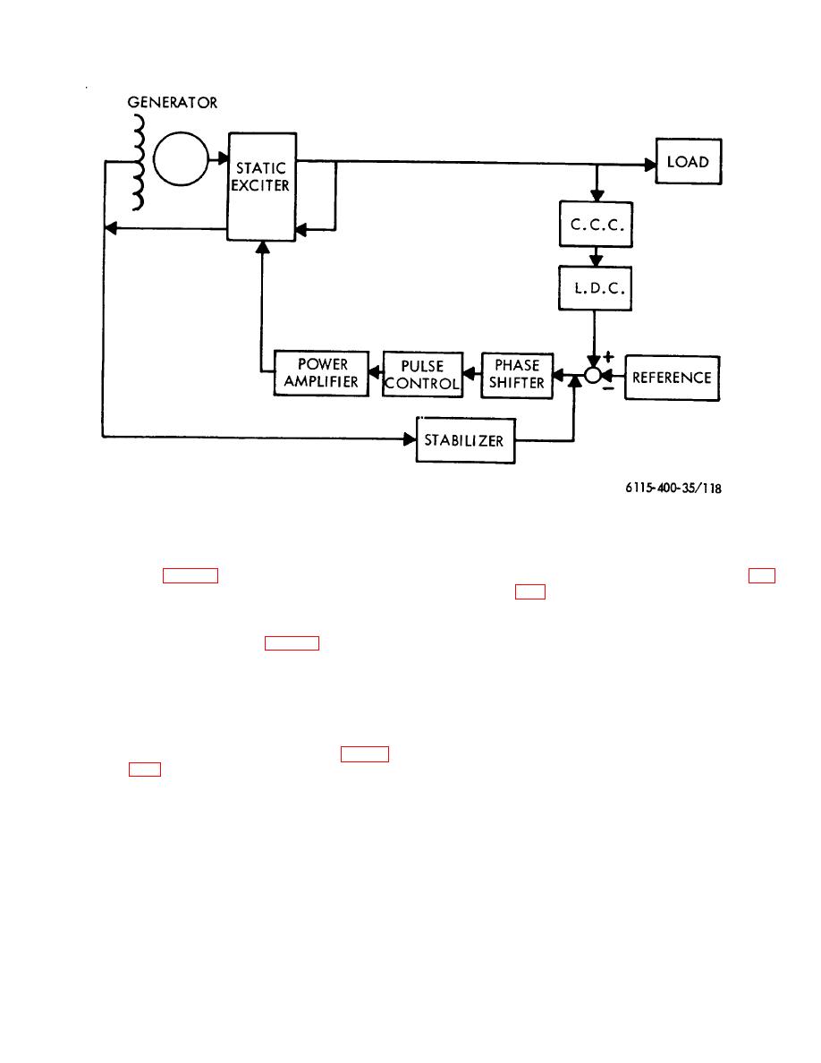
Figure 118. Voltage regulator and excitation unit-block diagram
A complete connection diagram of the excitation unit
under load. With the generator operating
and voltage regulator is provided in the wiring and
without load, winding P (I) and P (I') of the
schematic diagram, figure 1.
current voltage transformer (CVT; see fig.
are connected in series with any external
72. Static Exciter
load. Temporarily assuming the control
a. General.
winding S (C) is not used, the current
(1) The exciter assembly (fig. 119) is a static
voltage transformer becomes a simple
type and is mounted above the main
stepdown coupling transformer having a
generator.
rector (XL) connected in the primary circuit
(2) The static exciter consists basically of
P (V) and the secondary winding S (V)
three d.c.
controlled, single-phase,
supplying rectified current to the generator
current voltage transformers, (CVT), a
field.
linear three-phase reactor (XL) and a
(4) Operating under the above condition, the
three-phase, full-wave rectifier. Figure
generator would build up from zero
voltage to above rated voltage, reaching a
illustrating one third of the static exciter.
ceiling voltage in a manner similar to the
(3) The static exciter has two modes of
operation of a direct current shunt-wound
operation: One when the generator is
generator.
operating under no-load conditions, and
the other with the generator operating
152


