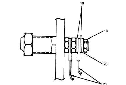
Figure 5-26. Load Terminal Board Stud Assembly
b. Test.
(1) Remote Battle Short Function.
(a)
(b)
(c)
(d)
(e)
(f)
NOTE
Refer to the Operator and Unit Maintenance Manual for generator set controls and
switches.
Close DC circuit breaker.
Place START–RUN-STOP switch in RUN position.
Place BATTLE SHORT switch in ON position.
NOTE
The electric fuel pumps should immediately start to run making a steady clicking
sound.
Connect test lead from positive terminal of generator set battery to pin D of connector J1 (8, figure
5-26).
Connect test lead from negative terminal of generator set battery to pin K of connector J1 (8).
NOTE
The AC circuit breaker indicator light should light and the electric fuel pumps should
continue to run.
Open AC circuit breaker switch.
NOTE
The AC circuit breaker indicator light should stay lit and the electric fuel pumps should
continue to run.
5-58
ARMY TM 9-6115-464-34
AIR FORCE TO 35C2-3-445-2
NAVY NAVFAC P-8-624-34