• Home
  • Download PDF
  • Order CD-ROM
  • Order in Print
Table 5-3. APPLICATIONS KIT TROUBLESHOOTING CHART
Figure 5-23. Plate and Sleeve Assembly Removal - TM-9-6115-464-34_458

TM-9-6115-464-34 Generator Set Diesel Engine Driven Tactical Skid Mtd 15 Kw 3 Phase 4 Wire 120/208 and 240/416 Volts Manual
Page Navigation
  430    431    432    433    434  435  436    437    438    439    440  
ARMY TM 9-6115-464-34 AIR FORCE TO 35C2-3-445-2 NAVY  NAVFAC  P-8-624-34 NOTES Insure the dust rover retaining chain (figure 5-25) on connector J1 is mounted on the lower right hand mounting screw of connector. A third lockwasher is added between the mounting nut and ground lug on connector mounting screw. 
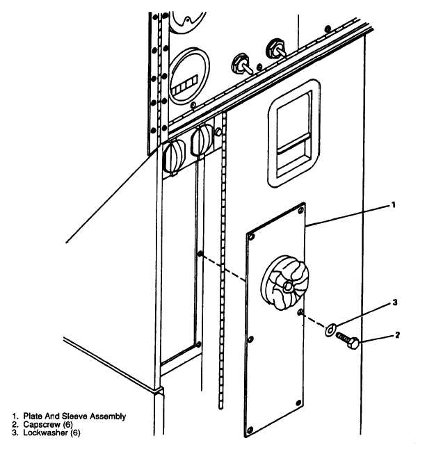
(e)  Mount  connector  plate  using  six  capscrews  (3)  and  Iockwashers  (4)  removed  from  plate  and  sleeve assembly. Figure 5-23. Plate and Sleeve Assembly Removal 5-54


Western Governors University

Privacy Statement
Press Release
Contact

© Copyright Integrated Publishing, Inc.. All Rights Reserved. Design by Strategico.