(g)
(h)
(i)
(j)
(k)
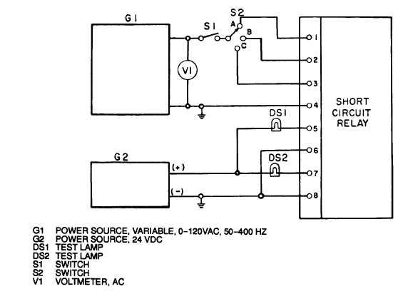
Figure 3-115. Short Circuit Relay Test Circuit
Place switch S2 in B position and dose switch S1.
Repeat steps (d) through (f).
Place switch S2 in C position and dose switch S1.
Repeat steps (d) through (f).
The voltage at which relay trips in step (e), (h) and (j) shall be within 1 volt.
(12) Test overload protective device as follows:
(a)
(b)
(c)
(d)
(e)
(f)
Install over load protective device in test circuit shown in figure 3-116.
Activate generator G2 and power source G1 and dose switch S1. Test lamp DS1 shall illuminate.
Adjust auto transformers T1, T2 and T3 until ammeters A1, A2, and S3 indicate 0.75 amperes
each.
Adjust auto transformer T1 until ammeter Al indicates 0.975 amperes. After 8 ± 2 minutes, test
lamp DS1 shall extinguish and test lamp DS2 shall illuminate.
Adjust auto transformer T1 until ammeter Al again indicates 0.75 amperes. Test lamp DS2 shall
extinguish and test lamp DS1 shall illuminate.
Repeat steps (d) and (e) for auto transformers T2, and T3. Result shall be the same as for T1.
(13) Replace any relay or protective device found to be defective.
(14) Test tactical relay resistor assembly as follows:
(a) Ccmnect one lead of an ohmmeter to terminal number (4, figure 3-117).
3-244
ARMY TM 9-6115-464-34
AIR FORCE 35C2-3-445-2
NAVY NAVFAC P-8-624-34