ARMY TM 9-6115-464-34
AIR FORCE TO 35C2-3-445-2
NAVY NAVFAC P-8-624-34
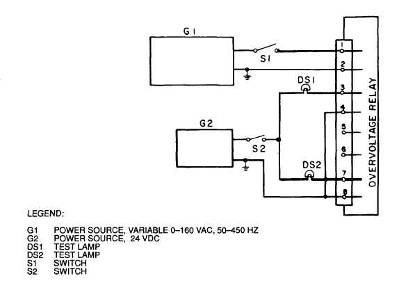
Figure 3-114. Overvoltage Relay Test Circuit
(h) Set output frequency of power source G1 to 50 Hz. Slowly increase output voltage to 156 volts.
DS1 shall extinguish and DS2 shall illuminate. Momentarily open switch S1 and allow relay to reset.
(i) Repeat step (h) for frequencies of 60,70 and 100 Hz.
(j) Set output frequency of power source G1 to 350 Hz. Increase output voltage to 151 volts ac. DS1
shall extinguish and DS2 shall illuminate. Momentarily open switch S1 and allow relay to reset.
(k) Repeat step (j) for frequencies of 400 and 450 Hz.
(11) Test short circuit relay as follows:
(a) Install short circuit relay in test circuit shown in figure 3-115.
(b) Activate power sources G1 and G2.
(c) Place switch S2 in the A position and close S1.
(d) Slowly increase output voltage of power source G1. Test lamp DS1 shall illuminate.
(e) Observe voltmeter V1 while continuing to increase voltage. At a voltage of 24 ± 1 Vac. test lamp
DS1 shall extinguish and DS2 shall illuminate.
(f) Return output voltage of G1 below 24 Vac and open A allowing the relay to reset.
3-243