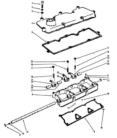
TM5-6115-593-34NAVFAC P-8-631-34TO-35C2-3-463-2LEGEND1.Screw2.Lockwasher3.Washer4.Cover5.Gasket6.Screw7. Washer8. Housing9.Gasket10.O-ring11.Plug12.Plug13.Plug14.Shaft15.Plug16.Pin17.Locknut18.Screw19. Bushing20.Rivet21.Lever22.Lever23. Lever24.Lever25. Nut26. Screw27.Bushing28.Socket29.LeverFigure 13-38. Rocker Arm Shaft and Rocker Arm Assembly,Exploded Viewposition and tighten nut with torque wrench to 25 to 35foot-pounds (34.6 to 41.5 joules).(9) Using a wire gauge, check to make surethere is a minimum of 0.020 inch (0.51mm) clearance between crosshead andvalve spring retainer.(10) Refer to the Operator/Crew andOrganizational Maintenance manual foradjustment and reassembly instructions.13-26.PUSHRODS AND TAPPETS. To inspect andreplace the pushrods and tappets, refer to figures 13-39and 13-40, and proceed as follows:a. Removal, Code A (Figure 13-39)(1) Lift crossheads.(2) Remove pushrods by lifting them from theirtappets.(3) Remove lockwires (3) and (10) and copperwashers (17) holding tappet guides (16).Discard copper washers.(4) Lift tappets (8) and (15) from block with along wire hook or other suitable tool.13-75
Integrated Publishing, Inc. - A (SDVOSB) Service Disabled Veteran Owned Small Business