TM 9-6115-604-34
NAVFAC P-8-633-34
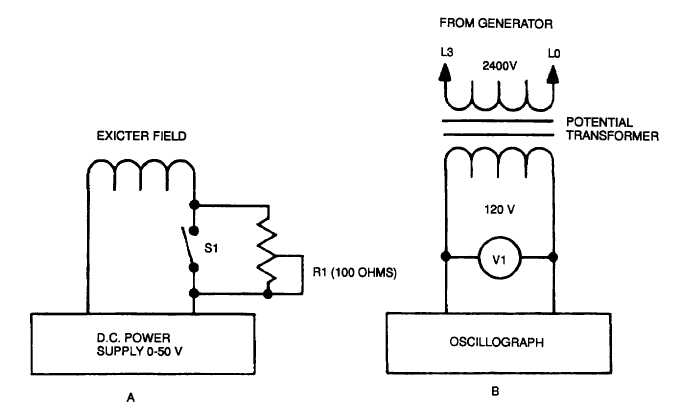
Figure 12-8. Voltage Divider Transformer Network
e.
Results.
(1)
From the oscillograrns made in step c, above, determine and tabulate the time between the application of the
overvoltage and operation of the circuit interrupter for each application of overvoltage.
(2)
From the oscillograms made in step d, above, determine and tabulate the time between the application of
the undervoltage and the operation of the circuit interrupter for each application of undervoltage.
(3)
Compare these results with the requirements of Table 12-3.
12-19. REVERSE POWER PROTECTIVE DEVICE.
a.
Reverse the wires on K109 terminals 5 and 6.
b.
Start the generator set and apply a 20 ±3 percent load.
c.
The reverse power relay should activate and open the load connector.
d.
Return the wires on K109 terminals 5 and 6 to their original location.
12-20. PHASE SEQUENCE (ROTATION).
a.
General. Unless the phase sequence (rotation) of the load terminals of a three-phase generator set is
correct, serious damage or injury could be done to connected equipment and to personnel as a result of
reversed motor rotation or excessive current surges.
b.
Apparatus. A phase sequence (rotation) indicator, or a three-phase motor whose direction of operation in
relation to phase sequence is known.
12-26