TM 9-6115-604-34
NAVFAC P-8-633-34
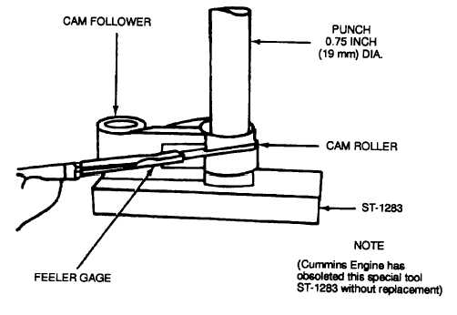
Figure 9-14. Removing and Installing Cam Rollers and Pins
(9)
Check the shaft bore of the follower (12 or 13) for scoring and galling. Replace any follower scored over
0.002 inch (0.05 mm) in depth.
(10)
Check the inside diameter of the shaft hole in the follower (12 or 13) for wear and out-of-round. Replace
the follower if the maximum diameter of the shaft hole is not in accordance with Table 1-4.
(11)
Check the rollers (18 or 20) for galling, flaking, or chipping at the outer edges of the rollers. Replace the
rollers for any imperfections noted.
NOTE
If galling, flaking, or chipping of the rollers is noted, the mating camshaft lobe should be
carefully inspected in accordance with paragraph 9-15.
(12)
Check the outside diameter of the rollers (18 or 20) for wear and out-of-round. Replace the roller if the
diameter is not in accordance with Table 1-4.
(13)
Measure and record the diameter inside of the rollers (18 or 20). Maximum diameter shall be in
accordance with Table 1-4. Out-of-round shall be within 0.002 inch (0.05 mm).
(14)
Check the pins (17 and 19) for scoring. Replace the pins if scored deeper than 0.002 inch (0.05 mm).
(15)
Measure and record the diameter of the pins (17 and 19). Minimum diameter shall be in accordance with
Table 1-4. Out-of-round shall be within 0.003 inch (0.08 mm). Replace undersize and out-of-round pins.
(16)
Subtract the measurement obtained in step (15), above, from that obtained in step (13), above; this is the
roller-to-pin clearance.
(17)
It the roller-to-pin clearance exceeds 0.0045 inch (0.114 mm), replace the pins (17 or 19), rollers (18 or
20), or replace both pins and rollers as necessary to obtain a clearance of 0.0030 to 0.0045 inch (0.076 to
0.114 mm).
(18)
Check the roller-to-follower side clearance. Replace the roller or follower, or both roller and follower, if the
side clearance exceeds 0.024 inch (0.61 mm).
(19)
Check the cam follower sockets (21) for wear using a new push rod (1 or 2) and Prussian blue compound.
The blueing pattern shall show in at least 80 percent of the socket area.
9-28


