TM 9-6115-604-34
NAVFAC P8-633-34
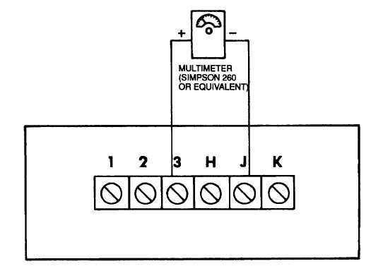
Figure 6-32. Test Setup, 50/60 Hz Module
c.
Precise Load Sharing Module. See Figure 6-33.
(1)
Start the engine and operate at 1 800 rpm and no load (2) Using a multimeter set to 0 to 250 V ac scale,
measure voltage across terminals 1 and 3, 1 and 5, and 3 and 5.
(3)
Multimeter should indicate nominal 208 V ac rms.
(4)
Using multimeter set to 0 to 50 V dc scale, measure voltage from terminal 17 to terminal 18.
(5)
Multimeter should indicate 10.2 0.6 V dc.
(6)
Using multimeter set to 0 to 10 V dc scale, measure voltage from terminals 14 to 17, 15 to 17, and 16 to
17.
(7)
Multimeter should indicate 5.1 0.3 V dc.
(8)
Replace a precise load sharing module which fails any of the tests described in steps (1) through (7),
above.
d.
Synchronizer A105. See Figure 6-34.
(1)
Disconnect terminal 14 lead from terminal board and insulate in order to prevent load circuit breaker CB1
01 from closing once voltage has been synchronized.
(2)
Connect the generator set to a five bus such as utility power.
(3)
Using a multimeter set to the appropriate scale, measure voltage and compare values obtained in
accordance with Figure 6-34.
(4)
Using a multimeter set to RX1 scale, measure resistance across terminals 13 and 14.
(5)
Multimeter should indicate greater than zero ohms.
(6)
Replace a synchronizer which fails any of the tests described in steps (3) through (5), above.
e.
Adjust Load Sharing Panel A104. To adjust load sharing panel A104, perform an operational checkout of the
generator set in accordance with the Operator and Organizational Maintenance Manual.
6-62