TM 9-6115-604-34
NAVFAC P-8-633-34
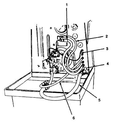
1.
OUTLET HOSE
4.
SUCTION VALVE
2.
HOSE TO PRESSURE GAGE
5.
SUPPLY HOSE
3.
RETURN HOSE
6.
HOSE TO VACUUM GAGE
Figure 6-16. Test Stand Hose layout
(10)
Loosen the adjusting screw nuts (25 and 27, Figure 6-11) and back out the setscrews (28) completely so
that they do not interfere with the free movement of the throttle shaft stop (34) on the throttle shaft (30).
(11)
Lightly damp a pair of locking pliers on the throttle shaft (30), and install a universal spring to hold the
throttle shaft in the fully open position (rotated fully clockwise) as in step (9), above.
(12)
Open the suction valve (4, Figure 6-16), set the rotation switch (2, Figure 6-17) for right hand rotation, and
press the start/stop light button (16).
(13)
Using speed control handle (4, Figure 6-15), adjust the pump speed to 500 rpm, and check the vacuum
gage (7, Figure 6-17) to be sure the fuel pump has suction. If the vacuum gage (7) does not indicate
suction, stop rotation and repeat step (5), above.
(14)
Increase the pump speed to 1700 rpm, and adjust the suction valve to give vacuum gage (7) reading of 8
inches (200 mm) Hg.
(15)
After 2 or 3 minutes of running time, check the main flowmeter (15) for the presence of air bubbles.
NOTE
It will take 2 to 3 minutes for the fuel pump to become completely primed and expel all air.
During this time, the presence of air bubbles in the main flowmeter is normal.
(16)
If the bubbles persist after 2 to 3 minutes of running time, a vacuum leak is indicated. Check and repair
vacuum leaks in the suction hoses before continuing.
(17)
Run the pump for 30 minutes and any additional time necessary to reach a test oil temperature of 90° to 1
000F (320 to 38"C) on fuel temperature gage (1).
6-35