TM 9-6115-604-34
NAVFAC P-8-633-34
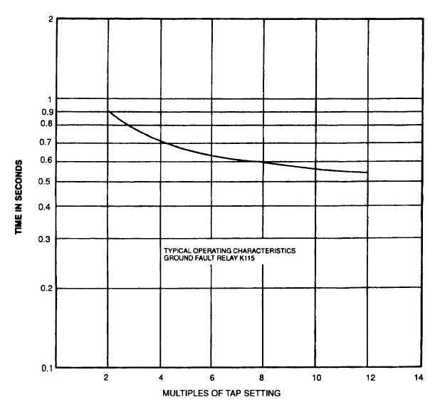
Figure 5-31. Ground Fault Relay K115, Time Voltage Curve
(3)
See Figure 5-32. Check tap for proper setting. Tap should be in the 2 ampere tap. If not, proceed as
follows:
(a)
The tap plug is the screw holding the right-hand stationary contact of the sealed-in element.
(b)
Take a screw from the left-hand stationary contact and place it in the 2 ampere tap.
(c)
Remove the screw from the other tap and place it in the left-hand contact.
(4)
See Figure 5-32. Verify that the time dial is set at the number 1 time dial position. If not, turn the time dial
until the number lines up with the notch in the adjacent frame.
(5)
See Figure 5-32. Verify that the tap plug is set at the number 16 position on the tap block. If not, remove
the tap plug and install it in this location.
b.
Remove. See Figure 5-9.
(1)
Tag and disconnect wires from ground fault relay K111 (67).
(2)
Remove ground fault relay K115 (67) cover by loosening captive screw and washer assemblies (68).
(3)
Remove ground fault relay K111 (67) by removing screws (66).
5-77