ARMY TM 9-6115-604-12
NAVY NAVFAC P-8-633-12
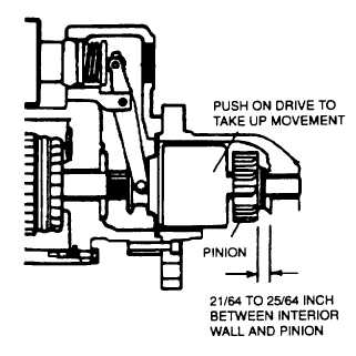
Figure 4-35. Checking Pinion Clearance
c.
Install.
(1 )
Replace starter motors B1 and B2 and starter slave relays K1 and K2, and secure to engine
assembly with machine bolts, washers, and lock washers.
(2)
Connect wiring as tagged In step a, above, to electrical solenoids, starter motors, and starter
relays. Discard tags.
(3)
Reconnect battery power.
SECTION IX. MAINTENANCE OF AC ELECTRICAL POWER GENERATION AND CONTROL SYSTEM
4-34.
GENERAL.
a.
Generator G1 Operation. See FO-2.
(1)
The generator is a brushless, 4-pole type, producing 60 Hz power at 1800 rpm or 50 Hz power at
1500 rpm. For 60 Hz operation, the generator produces 2400/4160 volts of 3-phase power in wye
configuration (2400 volts line-to-neutral, 4160 volts line-to-line). For 50 Hz operation, the generator
produces 2200/3800 volts of 3-phase power in wye configuration (2200 volts line-to-neutral, 3800
volts line-to-line).
(2)
AC generators require direct current flow through the rotor winding to set up the magnetic flux which
allows the unit to generate. A small exciter provides this direct current. The exciter is mounted on
the same shaft as the generator rotor. The main generator field rotates and the armature is fixed
while the exciter field is fixed and the armature rotates. The output from this exciter is fed into the
rectifying elements mounted on a heat sink. This rectifier assembly is located on the end of the main
shaft, opposite the drive end.
(3)
The ac exciter requires direct current for its excitation. This excitation is suppliers by rectifying a
portion of the output of the main generator by means of a static voltage regulator. The amount of
current going into the field of the exciter will determine the output voltage of the exciter, and this in
turn will control the output voltage of the main generator.
(4)
Current boost module A101 provides additional exciter field current if the generator output voltage
should fall below a set level.
4-90


