ARMY TM 9-6115-604-12
NAVY NAVFAC P-8-633-12
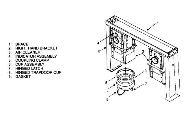
Figure 3-19. Air Cleaner Assembly
c.
Air Restriction Indicators. Indicator assemblies (4, Figure 3-20) are resettable Items and need not be replaced
except for obvious physical damage or the Inability to reset to green. The green, amber, and red color coding of the air
restriction Indicators Is Intended to Indicate the degree to which the air cleaners have become contaminated during the
filtration process. Green indicates an acceptable level of contamination. Amber or red Indicates an unacceptable level
of contamination. Refer to the next higher level of maintenance for maintenance of the air cleaners when the amber
portion of the indicator sleeve is visible through the sight window of the air restriction indicator.
d.
Air Control Valve.
(1) Inspect. Visually Inspect each air control valve (Figure 3-21) for secure mounting, damage, or rust.
CAUTION
Do not perform this test on a hot engine. if engine has been running at
operational temperature, allow generator set to run at no load for at least 5
minutes before performing the test. This will allow the engine time to cool and
will prolong engine life.
(2) Test. While engine is operating, depress EMERGENCY SHUTDOWN pushbutton S7 to trip shut down
valves. Air valves must shut down engine. Manually reset valves to open position after test.
e.
Maintenance of Rocker Housing Covers.
(1) Inspect.
(a) Visually inspect rocker housing covers (1, Figure 3-22) for evidence of cracks.
(b) Inspect area of rocker housing cover gasket (2) for leaks. Replace leaking gasket In accordance with
step.
(2) below.
(c) Check capscrews (3 and 4) for damage and proper torque, 30 to 35 pound-feet (41 to 47 newton-meters).
Replace damaged capscrews.
3-56