ARMY TM 9-6115-464-34
AIR FORCE TO 35C2-3-445-2
NAVY NAVFAC P-8-624-34
d. Assembly.
(1)
(2)
(3)
(4)
(5)
(6)
(7)
(8)
(9)
(lo)
(11)
(12)
(13)
(14)
(15)
Install transformer (59, figure 5-7), screw and captive washer assembly (58) and nut (57), on chassis
(60).
Install relay insulator (56), power relay (55), screw (54), shoulder washer (53) and nut (52).
Position wiring harness (51), and install attaching screw and cpative washer assemblies (46 and 49)
and nuts 48 and 50). Install protective cap chain (47).
Install split gormmet (44) in heat sink bracket (45).
Postion heat sink bracket (45) in chassis (60) and install attaching screw and captive washer
assembly (25).
Position heat sinks (42) and install shoulder washers (43), screw and captive washer assemblies
(41), shoulder washer (40), flat washer (39) and nut (38).
Install semiconductors (37 and 33), Iockwasher (36) and tooth Iockwasher (32), flat washers (35 and
31) and nuts (34 and 30).
Install cushion clamp (29), screw and captive washer assemblies (28 and 27), nut and captive
washer assembly (26), and screw and captive washer assembly (25).
Install cover (24) and screw and captive washer assembly (23).
Install nut (20), tooth Iockwasher (21), indicator light base (19), nut (18), lamp (17) and lens (16) on
panel (22).
Install fuseholder (15), tooth Iockwasher (14), nut (13), fuse (12) and fuseholder cap (11).
Install circuit breaker (10), tooth Iockwasher (9), and nut (8) on panel (22).
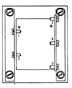
Install switch (7), nut (6), positioning washer (5), tooth Iockwasher (4) and nut (3) on panel (22).
Install panel (22) on chassis (60) and secure with Iockwashers (2) and screws (1).
Connect electrical leads.
e. Installation. Refer to the Operator and Unit Maintenance Manual for electric winterization kit heater control
assembly installation instructions.
Figure 5-8. Transformer Test Points
5-24