ARMY TM 9-6115-464-34
AIR FORCE TO 35C2-3-445-2
NAVY NAVFAC P-8-624-34
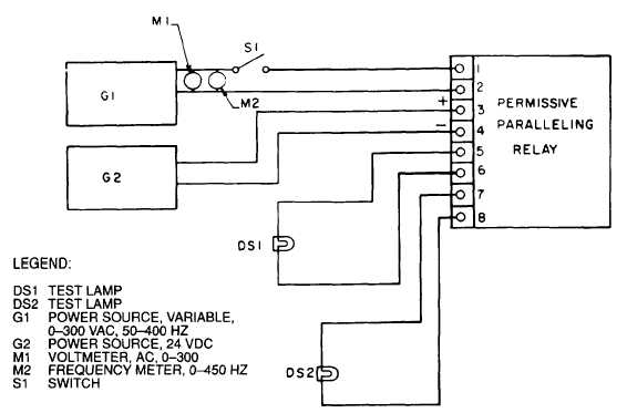
Figure 3–1 26. Permissive Paralleling Relay Test Circuit
(15) Check individual wires for continuity. Replace defective wires using wire conforming to Military
Specification MIL-W–5086, Type Il. Use figures 3-128 or 3-129 as a guide.
d. Assembly..
(1)
(2)
(3)
(4)
(5)
(6)
(7)
(8)
(9)
(10)
Position chassis (33, figure 3-123) to install permissive paralleling relay (32) and screw & captive
washer assembly (31).
Install under frequency relay (30), screw & captive washer assembly (29).
Install terminal jumper (28), terminal board assembly (27), screw (26), nut & captive washer
assembly (25).
Install electronic components assembly (24), screw & captive washer assembly (23) and nut (22).
Install under voltage relay (21), screw& captive washer assembly (20).
Install wiring harness (19), screw & captive washer assembly (18), and nut (17).
Install screw (16), nut & captive washer assembly (15), flatwasher (14), nut & captive washer
assembly (13).
Install switch (12), positioning washer (11), tooth Iockwasher (10) and nut (9).
Install rheostat (8), tooth Iockwasher (7), nut (6), and locknut (5).
Install cover (4), screw & captive washer assembly (3).
e. Installation.
(1) Position precise relay assembly to install Iockwashers (2, figure 3-123) and screws (1).
(2) Connect electrical connectors to precise relay assembly.
3-263


