ARMY TM 9-6115-464-34
AIR FORCE TO 35C2-3-445-2
NAVY NAVFAC P-8-624-4
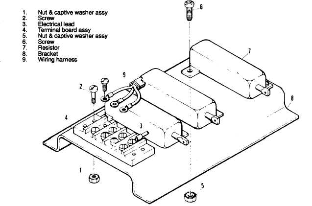
Figure 3-118. Tactical Relay Resistor Assembly, Exploded View
(16) Test dc relay assembly as follows:
(a)
(b)
(c)
(d)
(e)
(f)
(g)
(h)
(i)
(j)
(k)
(l)
(m)
Apply 24 Vdc to terminals 6 and 15 (figure 3-121).
Use an ohmmeter to check for continuity across terminals 5 and 17.
Check for open circuit across terminals 4 and 16.
Install a jumper between terminals 9 and 6.
Apply 24 Vdc to terminals 12 and 15 with 12 positive.
Check for continuity between terminals 5 and 17 and for open curcuit between terminals 4 and 16.
Install a jumper between terminals 23 and 6.
Apply 24 Vdcto terminals 21 and 15 with 21 positive.
Check for continuity between terminals 5 and 17 and for open curcuit between terminals 4 and 16.
Apply 24 Vdc to terminals 13 and 15.
Check for continuity between terminals 1 and 14 and between terminals 2 and 15. Check for open
curcuit between terminals 3 and 15.
Apply 120V AC to terminals 18 and 22. Use an ohmmeter check for resistance of 2,500 ohms
between terminals 19 and 20 and 7 and 8.
Check resistors R3, R6, and R9 for correct values given in figure 3-121.
(17) Replace defective dc relay assembly components (iterns 1 through 21, figure 3-122).
3-249