ARMY TM 9-6115-464-34
AIR FORCE TO 35C2-3-445-2
NAVY NAVFAC P-8-624-34
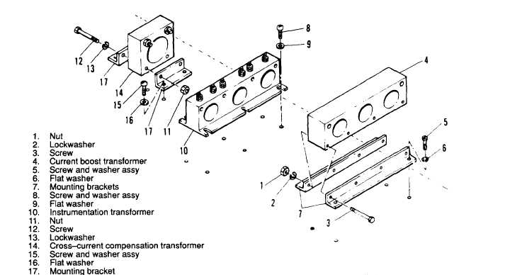
Figure 3–108. Transformer assemblies, Removal and Installation
b. Cleaning. Inspection. and Testing.
(1) Clean transformer assemblies with a clean, lint-free cloth moistened with an approved solvent and
dry thoroughly.
(2) Inspect transformer assemblies for cracks, corroded terminals, and evidence of shorting.
(3) Test current boost transformer as follows:
(a) Using an ohmmeter, check resistance between terminals A1 and A2, B1 and 62, and C1 and C2,
figure 3-109. Resistance shall be 0.19 ohm in each case.
(b) Apply 7V-60 Hz to secondary winding. Excitation current shall be 0.075 amp (maximum).
(4) Test instrumentation transformer as follows:
(a) Using an ohmmeter, check resistance between terminals A1 and A2, B1 and B2, C1 and C2 (figure
3-102). Resistance shall be 0.11 ohm in each case.
(b) Apply 10V-60 Hz to secondary winding. Excitation current shall be 0.050 amp (maximum).
(5) Test cross-current compensation transformer as follows:
(a) Using an ohmmeter, check resistance between terminals. Resistance shall be 0.3 ohm.
(b) Apply 10V-60 Hz to secondary winding. Excitation current shall be 0.050 amp (maximum).
(6) Replace defective or damaged transformers.
3-233