ARMY TM 9-6115-464-34
AIR FORCE 35C2-3-445-2
NAVY NAVFAC P-8-624-34
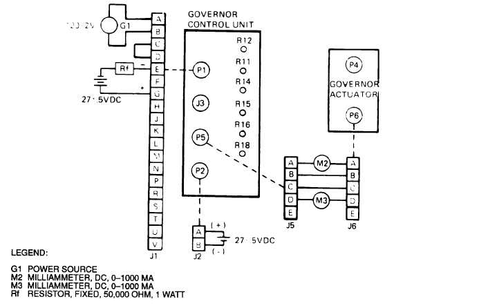
Figure 3-80. Electro-Hydraulic Governor Control Unit Parallel Winding Test Circuit
(2) Position governor control unit to install threaded rod (6, figure 3-68), bracket (5), Iockwashers (4),
nuts (3), Iockwashers (2) and nuts (1).
(3) Connect electrical connectors to governor control unit and untag.
NOTE
Desired speeds must be obtained by trial and error adjustments of linkage, position of
control arm and performing the alignment procedures in paragraph 3-64j.
j. Alignment Procedure. See figure 3-83 for identification of controls and perform the following procedures.
(1) Set R11, R14, R16 and R18 rheostats at mid-point.
(2) Set R15 full counterclockwise.
(3) Set R12 approximately 3/4 turn counterclockwise.
(4) Refer to Unit Maintenance Manual and start engine. If engine oscillates rapidly, adjust R16 and R18
until operation is stable.
(5) Once set has been stabilized, adjust R1 rheostat on control panel to obtain 60 Hz or 400 Hz.
(6) Connect a dc voltmeter with 0-10 volt range across test points 3 and 4. Test point 4 is positive.
Adjust R14 until voltage across test points 3 and 4 is zero at no load.
3-180