ARMY TM 9-6115-464-34
AIR FORCE 35C2-3-445-2
NAVY NAVFAC P-8-624-34
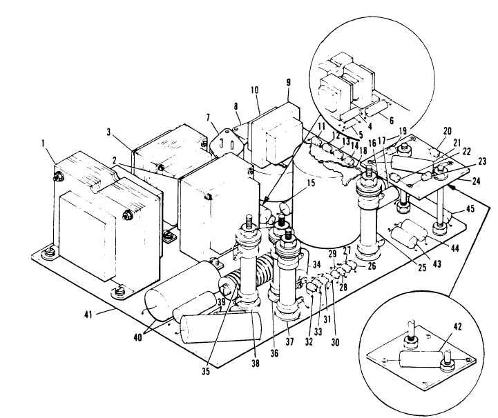
1. Power transformer (T1)
2. Filter reactor (L2)
3. Filter reactor (L1)
4. Fixed capacitor (C7)
5. Resistor R23)
6. Resistor (R5)
7. Power transistor (Q1)
6. Power transistor (Q2)
9. Reactor
10. Transformer (T2)
11. Silicone rectifier (CR5)
12. Silicone rectifier (CR6)
13. Silicone rectifier (CR4)
14. Silicone rectifier (CR3)
15. Fixed capacitor (C9)
16, Resistor (R20)
17. Resistor (R22)
18. Magamp (AR1)
19. Silicone rectifier (CR7)
20. Silicone rectifier (CR9)
21. Resistor (R37) (50/60 Hz)
22. Silicone rectifier (CR8)
23. Silicone rectifier (CR10)
24. Panel assembly
25. Adjustable resistor (R10) (50/60 Hz only)
26. Silicone rectifier (CR15)
27. Silicone rectifier (CR16)
28. Silicone rectifier (CR17)
44. Resistor (R4)
29. Silicone rectifier (CR18)
45. Capacitor (C5)
30. Silicone rectifier (CR11)
31. Silicone rectifier (CR12)
32. Silicone rectifier (CR13)
33. Silicone rectifier (CR14)
34. Fixed capacitor (C6)
35. Selenium rectifier (CR12)
36. Power resistor (R1)
37. Adjustable resistor (R2)
38. Power resistor (R1A)
39. Fixed capacitor Cr) (400 Hz unit only)
40. Fixed capacitor (C3)
41. Printed circuit board
42. Fixed capacitor (C2)
Figure 3-71. Electro-Hydraulic Governor Control Unit Printed Circuit Board
3-170
43. Resistor (R8)