ARMY TM 9-6115-464-34
AIR FORCE TO 35C2-3-445-2
NAVY NAVFAC P-8-624-34
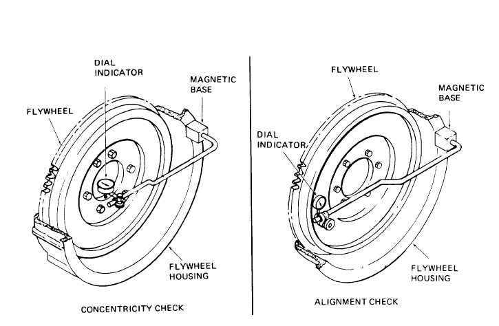
Figure 3-43. Checking Flywheel Concentricity and Alignment
3-51. TIMING GEARS AND COVER.
a. Removal and Disassembly.
(1)
(2)
(3)
(4)
(5)
(6)
(7)
(8)
(9)
Remove the hydraulic pump assembly (paragraph 3-41).
Remove the fuel injector nozzle from No. 1 cylinder.
Turn the engine over until the 20 degree before top dead center (BDC) mark on the engine flywheel
is aligned with the timing mark on the flywheel housing and No. 1 cylinder is on compression stroke.
Remove the front engine support (paragraph 3-49).
Remove screws (1, figure 3-44) and Iockwashers (2) to remove fuel pump thrust plate (3), gasket
(4), thrust button (5) and spring (6). Discard gasket.
Remove screws (7, 9, 11, and 13), screws (15), and Iockwashers (8, 10, 12, 14, and 16) to remove
timing gear cover (17) and gasket (18). Discard gasket.
Press seal (19) from cover and discard.
Remove nut (20) and Iockwasher (21) to remove fuel pump drive gear (22).
Remove screw (23) and washer (34) to remove idler assembly (25).
3-105