ARMY TM 9-6115-464-34
AIR FORCE TO 35C2-3-445-2
NAVY NAVFAC P-8-624-34
d. Asssembly.
CAUTION
When installing seal, press on outer flange to avoid damaging the seal. Failure to
observe this caution could result in equipment damage.
(1) Press replacement seal (11) into pump body (12).
CAUTION
When installing shaft and bearing assembly, press on outer bearing face and not on
end of shaft. Failure to observe this caution could result in equipment damage.
(2) Press shaft, bearing and flinger assembly (9) into pump body and install retaining ring (2).
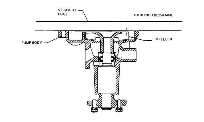
(3) Support pump on outer end of shaft and press impeller (10) onto shaft, bearing and flinger assembly
to obtain 0.010 inch clearance between impeller and cover plate (figure 3-29).
(4) Install gasket (8) and cover plate (7) and secure with screws (3). Install bracket (6) with screw (4)
and washer (5).
(5) Press pulley hub (1) onto shaft (9) until shaft is flush with front of pulley.
(6) Install water inlet housing (15) and new gasket (16) with screws (13) and Iockwasher (14).
e. Installation. Refer to the Operator and Unit Maintenance Manual for water pump installation procedures.
Figure 3-29. Checking Impeller to Cover Plate Clearance
3-74


