TM5-6115-634-14&P
NAVFAC P-8-647-14&P
T0-35C2-3-445-14
TM-6115-14&P/1
MAINTENANCE OF EXHAUST BAFFLE ASSEMBLY
4-23.
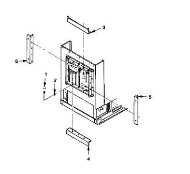
REPLACE EXHAUST BAFFLE MOUNTING BRACKETS
This task covers: a. Removal
b. Installation
INITIAL SETUP
Tools
Equipment Conditions:
Reference
General Mechanic’s Tool Kit
Para. 4-22 Remove Exhaust Baffle Assembly.
5180-00-177-7033
Materials/Parts
Flange Top Exhaust Baffle Assy
97403-13228E1964
Flange Side Angle Exhaust Baffle Assy
97403-13228E1965 (2 ea.)
Flange Bottom Exhaust Baffle Assy
97403-13328E1966
REMOVAL
1.
REMOVE TOP FLANGE.
Remove five screws (1) and lock-
washers (2) and remove top flange
(3).
2.
REMOVE BOTTOM FLANGE.
Remove three screws
lockwashers (2) and
bottom flange (4).
(1) and
remove
3.
REMOVE SIDE ANGLE FLANGE.
Remove 10 screws (1) and
lockwashers (2) and remove
two side angle flanges (5).
INSTALLATION
1.
INSTALL SIDE ANGLE FLANGE.
Install two side angle flanges
(5) with 10 screws (1) and
lockwashers (2).
4-31