TM5-6115-634-14&P
NAVFAC P-8-647-14&P
T0-35C2-3-445-14
TM-6115-14&P/1
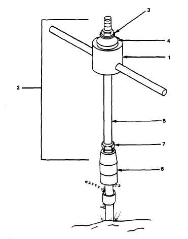
Nuts must be tight on the slide
hammer rod.
Loose hardware may
result in serious injury.
(3) Place the striker plate (4)
on the slide hammer assembly and replace
the nut (3) on the slide hammer rod.
(4) Connect the slide hammer
assembly (2) and slide hammer with the
striker plate at the top to the ground
rod coupler (6).
(5) Use the Slide hammer to lift
the ground section from the ground.
(6) Disconnect the ground rod and
remove nut (7).
(7) Remove the slide hammer from
the slide hammer assembly and store it
on the front of the trailer.
(8) Return the nut (7) to slide
hammer assembly and store the assembly
in the accessory box.
Reset curbside
handbrake.
Section IV.
OPERATION UNDER UNUSUAL CONDITIONS
2-8. Mobile Operations
In mobile operations, the PU 794/G sup-
plies power while being towed over the
highway.
The operation of the PU 794/G
is the same as normal operation.
Two
units cannot be paralleled while in
mobile operation.
The equipment being
powered must be grounded to the genera-
tor set of the PU 794/G. Care must be
taken in the routing of the power, con-
trol and ground cables from the PU 794/G
to the shelter to preclude damage while
the vehicle is moving. To prepare for
mobile operation connect the cables as
follows:
a.
Connect the ground cable to the
GROUND stud on the connector plate
(Figure 2-3).
b.
Connect the 5-foot (1.52 meter)
power cable between the power connector
of the connector plate and unit 1 power
connector on the junction box (Figure
2-3).
c.
Connect the 25-foot (7.62 meter)
power cable to the load connector of the
junction box (Figure 2-3).
d.
Remove the shorting plug and store
in the storage shorting plug connector
on the connector plate (Figure 2-3).
e.
Connect the 5-foot (1.52 meter)
control cable between the connector
plate control connector and the unit 1
control connection on the junction box
(Figure 2-3).
2-18