TM5-6115-593-34
NAVFAC P-8-631-34
TO-35C2-3-463-2
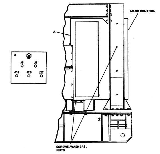
Figure 2-2. AC-DC Control Box Assembly, Removal and Installation
WARNING
OVERHEAD OPERATIONS HAVE INHERENT HAZARDS THAT CANNOT BE MECHANICALLY
SAFEGUARDED. HARD HATS AND SAFETY SHOES ARE REQUIRED.
panel in accordance with Chapter 15.
(2)
Referring to figure 2-3, remove all screws, washers, and nuts attaching reconnection box and enclosure to the
external power box assembly.
(3)
Disconnect and tag all cables from reconnection box, circuit breaker, and cable tiedown at base of external
power box assembly.
(4)
Remove cables through sleeves and at front of generator set.
(5)
Disconnect electrical connectors J27 through J31 (and J32, if generator set is equipped with housing).
(6)
Disconnect buss bars (39, 42, and 45, figure 11-1) from the circuit breaker by removing screws, washers, and
nuts that attach bars to
2-9