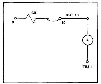
Figure 6-7. AC Output Control Box Test Setup
(12) Output-Control Box Housing (24, figure 6-9).
Inspect output control box housing for physical damage.
Check that all hingeq covers, and latches operate properly.
Check that all nameplates are in place. Check that side
access cover is alwavs in date when box is being actively
serviced.
b. Test.
(1) Reconnection Switch (S6) (1, figure 6-10). Tag
and disconnect electrical connections except jumper wires
from reconnection switch. Using an ohmmeter check for
continuity between terminals listed in table 6-5 for each
of the three switch positions. If continuity is not found for
each pair of terminals listed, replace reconnection switch.
If continuity is found between any other terminals switch
should be replaced.
(2) AC Circuit Breaker (CB1). Test that breaker will
remain in both the ON and OFF positiona.
(3) 15 Amp Circuit Breaker (CB3). Test that breaker
will remain in both the set (pushed) and tripped (pulled)
positions.
(4) Convenience Receptacle (J14). With 15 amp
circuit breaker in proper operating position, test con-
venience receptacle using a 120 volt trouble light or
voltmeter.
With the unit operating and the 15 amp
circuit breaker pushed in, 120 volts should be present
at the receptacle.
(5) Linear Reactor (Ll). Disconnect electrical
connectors from control box. Use an ohmmeter to check
TM5-6115-585-34
NAVFAC P-8-623-34
TO-35C2-3-455-2
TM-05684C/05685B-34
resistance of each of the three windings in the reactor
by checking resistance between terminals 1 and 2, 3 and
4, 5 and 6. Resistance for each winding must be 13.5 ohms
plus or minus 1.35, if not replace reactor.
(6) Connector Assemblies. Test for continuity
between each pin and case for shorts to ground.
(7) Current Voltage Transformer (CVT1). Using an
ohmmeter check three primary windings of transformer
(figure 1-1, 6-7.1 and 6, figure 6-9) by measuring resistance
from terminals H1 to H2, H3 to H4, H5 to H6. Resistance
must be 2.27 ohms ± 0.227 ohms. Check resistance in three
secondary windings of transformer by checking from
terminals Xl to X2, Xl to X3, X2 to X3. Resistance
must be 1.68 ohms ± 0.168 ohms. Check resistance in
control windings by checking from terminals Cl to C2.
Resistance must be 9.6 ohms ± 0.96 ohms. If any of the
windings do not show the proper resistance, replace
transformer.
(8) Current Transformer (CT1). On the current
transformer (figures 1-1, 6-7.1 and 7, figure 6-9) only the
secondary windings can be checked. Using an ohmmeter
check resistance in secondary windings by checking from
terminals 1A to 2A, lB to 2B, lC to 2C. Resistance must
be 0.5 ohms ± 0.05 ohms. If any of the windings do not
show the proper resistance, replace transformer.
(9) Bridge Rectifier Assembly (A4) (see figure 6-11).
Tag and remove leads to terminal board and test each
diode (3) separately by checking between terminals (6)
shown in table 6-6. Resistance in one direction should be
very high in one direction and very low in the other.
Measure resistance of R1 (4). It should be 56 ohms.
Change 5
6-15