TM5-6115-584-34
NAVFAC P-8-622-34
TO-35C2-456-2
(8) Slide spring (35), pinion gear (34) and
Stopper (33) onto shaft. Position retaining ring
(32) in groove on shaft and pull stopper over
ring to secure it. A bearing puller tool may
be required.
(9) Place bearings (16) and (18) on the
armature shaft, and insert armature into the
center bracket. Slide Stator (15) over armature
and into center bracket. Align stator to bracket
by fitting tab on stator into notch on center
bracket.
(10) Place brush holder (14) with brush
springs (12) in place, over the communtator of
the armature. Lift each brush spring (12) and
insert brush (13) into the guide on the brush
holder (14).
(11) Place rear cover (11) over brush holder
and against stator (15). Rotate slighly and align
threaded holes in brush holder with holes in
cover. Secure brush holder to cover with screws
(l0).
(12) Pass thru studs (9) through rear cover
(11) into tapped holes in front bracket assembly
(37) and secure.
(13) Place washers (7) on thru studs, place
terminal bracket assembly (8) on studs and add
nuts (6).
(14) Place spacers (4) on solenoid switch (5)
and align solenoid plunger slot over lever (30).
Secure solenoid and spacers to front bracket
assembly (37) with screws (3).
(15) Install field coil lead from stator (15)
onto lower threaded terminal of the solenoid (5).
Secure with nut (1) and washer (2).
J. Test after Repair/Overhaul. Style I Starter.
(1) After the starter is assembled, check
the armature end play by inserting thickness
gauge between thrust washer (27) and pinion
housing (28). See figure 5-1. It should be bet-
ween 0.005 and 0.035 inch. Adjust end play by
adding or removinq thrust washers (27) on the
communtator end of the Armature.
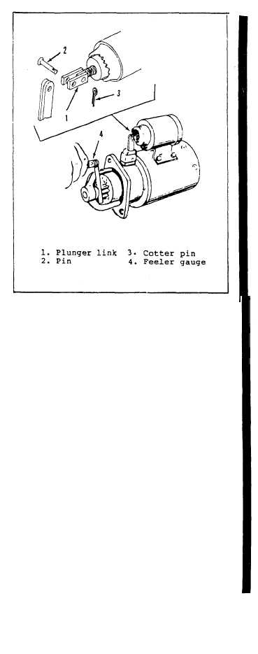
(2) Check pinion gear clearance. See figure
5-13. Proper clearance is important to insure
starter engagment. To check, press on solenoid
plunger to shift pinion gear into full mesh posi-
tion. While holding plunger in, measure clearance
with feeler gauge (4) between pinion gear and
stop. The proper clearance is 0.096 ±0.030/-0.020
inch. Adjust clearance by turning solenoid plunger
link (1) in to decrease gap, or out to increase
the gap.
See figure 5-13 cutaway view. Reinstall
the pin (2) and cotter pin (3) securing plunger
link (1) to yoke.
Figure 5-13 Checking Pinion Clearance.
STYLE I Starter
K. Test after Repair/Overhaul. Style II Starter.
(1) After starter is assembled, check the
pinion gear travel to ensure proper starter enga-
gement. See figure 5-14.
(a) To measure, provide as 24 volt DC power
source, such as battery. connect the positive "+"
battery to the solenoid terminal (S) with a
electrical lead that includes a
momentary switch.
(b) Connect the negative “-” battery ter-
minal to the ground terminal (G), with electrical
lead.
(c) Remove nut and lockwasher from terminal
(M), than remove and secure lead (L) away fran the
solenoid.
(d) Close and hold the momentary switch to
apply power to terminal (S) forcing the solenoid
plunger to pull the lever and move the pinion gear
forward. Measure the distance between mounting
surface of starter front bracket and outer edge of
pinion gear to determine the maximum travel (X).
Release the power source and the internal springs
will move lever to original position, returning
the pinion gear to its at rest position. Measure
this distance (Y). The difference between measur-
emsnt (X) and (Y) should fall within the nominal
travel distance (Z) of l7mm + or - 1mm.
Change 7
5-11


