a. See figure 14-16 and connect the electric
starter in the no-load test circuit illustrated. Per-
form no-load test as follows:
(1) Energize the test circuit and obtain a voltage
of 22 volts by varying the variable resistance.
(2) Check the speed of the armature on the
tachometer.
Minimum speed should be 7000 rpm.
(3) Check the current draw on the ammeter.
Maximum current draw should be 90 amperes. If a
low-speed, high-current condition exists, possible
causes are excessive armature arcing, armature
ground, armature short, or armature drag caused
by loose pole shoes or faulty bearings. A low-speed,
low-current condition indicates faulty brushes or
faulty connection.
b. See figure 14-16 and setup for lock torque
ted as illustrated.
CAUTION
Never operate the electric starter with all
resistance removed from the circuit. Fail-
ure to adhere to this caution will result in
extreme motor speeds which can cause
damage to the motor and possible injury to
personnel.
The variable resistance should be
one with a high current capacity.
(1) Energize the circuit and check the scale to
determine the torque output of the motor.
(2) Scale should indicate 22 pound-feet (mini-
mum), at 400 amperes and approximately four volts,
as indicated on the meters.
C. Installation. Install the starter motor on the
flywheel housing using the disassembly steps in re-
verse order. See figure 14-9.
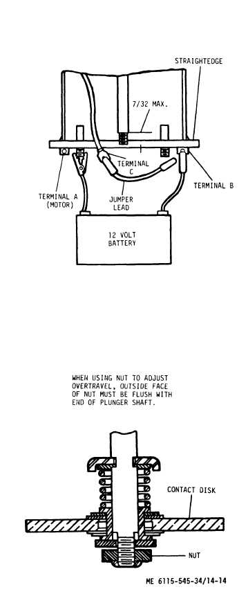
Figure 14-14.
Solenoid Adjustments
14-21