2-5. Installation and Setting-up Instructions.
a . General. The engine generator set should be
installed on a level site, clear of obstacles, and with
ample ventilation.
The site must be within 25 feet
of any paralleled generator set, 25 feet of any auxi-
liary fuel supply and 500 feet of any remote control
area.
b . Outdoor Installation. When preparing for a
permanent installation, be sure the base is solid
enough to support the weight of the unit. See figure
2-1 for dimensions of the base. Select a location
where there will be sufficient space on all sides for
servicing and operation of the engine generator set.
When preparing a temporary installation, move the
engine generator set as close to the worksite as
practical. Use suitable planks, logs, or other
material for a base in an area where the ground is
soft .
c. Indoor Installation. Keep the area well venti-
lated at all times, so that the engine generator set
will receive a maximum supply of air. If a free
supply of fresh air is not available, provide duct
work, with an opening at least as large as the radiator,
to the outside of the installation. If louvers are used
at the air entrance, increase the duct work size by
25 to 50 percent.
Loosen the screw and nut which
secure the weather cap to the exhaust outlet and re -
move the weather cap. Install a gas-tight metal pipe
exhaust from the exhaust outlet to the outside of the
installation.
The termination of the exhaust pipe
shall be such that hot gases or sparks will be dis -
charged harmlessly and will not be directed against
combustible material or into an area containing
flammable gases or vapors. Use as few bends in
the pipe and as short a pipe as possible. The ex-
haust pipe should include a low point with suitable
means for draining of condensate. Provide metal
shields, 12 inches larger in diameter than the ex-
haust pipe where the line passes through flammable
walls. Wrap the exhaust pipe with asbestos if there
is any danger of anyone touching it. Refer to figure
2-1 for dimensions, air flow requirements and floor
loading requirements.
WARNING
Do not operate the engine generator set in an
enclosed area unless the exhaust gases are
piped to the outside. Inhalation of exhaust
fumes will result in serious illness or death.
d. Leveling,
The engine generator set is a
portable unit and is designed to operate satisfactorily
up to 15° out-of-level. Set up the unit as level as
possible and keep it as level as possible during
operation.
e. Grounding. The engine generator set must be
grounded prior to operation. The ground can be, in
order of preference, (1) an underground metallic
water piping system, (2) a driven metal rod or
(3) a buried metal plate (fig. 2-2). If the effectively
grounded portion of the buried metallic water pipe
is less than 10 feet due to insulated sections or
joints, this preferred grounding method must be
supplemented by an additional driven metal rod
ground or a buried metal plate ground. A driven
metal ground rod must have a minimum diameter
of 5/8 inch if solid or 3/4 inch if pipe, and driven
to a minimum depth of 8 feet. A buried metal
ground plate must have a minimum area of 9 square
feet, minimum thickness of 1/4 inch, and be buried
at a minimum depth of 4 feet. The ground lead
must be at least No. 6 AWG (American Wire Gauge)
copper wire. Ground rods are available as optional
equipment. The procedures for making a ground
connection are shown in figure 2-2.
f. Generator Load Connections. Instructions
for making the required generator load connections
are designated in figure 2-3.
2-6. Equipment Conversion.
a. Conversion instructions for equipment opera-
tion at 120/208 Vac or 240/416 Vac are given in
figure 2-4.
b . Conversion instructions for equipment opera-
tion of 50 or 60 Hz are given in figure 2-6.
c. Conversion instructions for remote operation
by removal and relocation of the control cubicle are
given in paragraph 2-23.
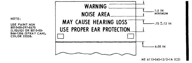
Figure 2-1A. Noise level warning.
Change 2
2-3