TM5-6115-465-34
NAVFAC P-8-625-34
T . O . 35C2-3-446-2
TM 06858B/06859D-34
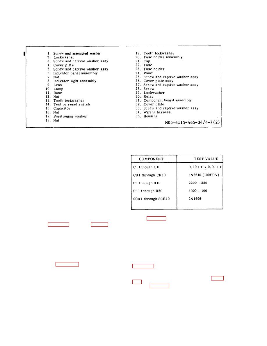
Fault Locating Indicator, Exploded View (Sheet 2 of 2)
Figure 4-7.
Table 4-1.
COMPONENT BOARD TEST VALUES
(b) Inspect Indicator fights for cracked
or damaged lens, defective lamp, and corroded or
damaged base.
(c) Inspect fuse holder assembly for
cracked or damaged cap, defective fuse, and burned,
cracked or corroded fuse holder.
(d) Inspect, test, or reset switch for
cracks, corrosion, and evidence of shorting.
(e) Check continuity of test or reset
switch using flgure 4-8 as a guide.
(5) Inspect component board assembly for
burned components, damaged wires and cracked or
broken board.
(8) Use an ohmmeter to test resistance of re-
lay K1 (figure 4-8). Resistance shall be 300 30
(6) Test individual components of component
ohms. Replace relay if defective.
board using figures 4-8 and 4-9 and table 4-1 as a
guide.
(9) Visually inspect fault locating wiring har-
ness connector for cracks, corrosion, and loose or
NOTE
damaged pins.
Disconnect one lead to component being
(10) Check individual wires for corroded or
tested to avoid erroneous test readings.
damaged terminals, burned insulation and other
damage.
(7) If any circuit board component must be
replaced or encapsulating coating repaired or re-
(11) Check individual wires for continuity using
placed, refer to Appendix A references for detailed
figure 4-10 as a guide.
procedures. Repair/replace encapsulation by
applying a O. 007 inch (minimum) coating of poly -
(12 ) If the wiring harness has sustained dam-
ureathane resin (Scotchcoat 221, Minnesota Mining
age and requires repair or rebuild, refer to figure
and Mfg. Co., or equal).
ments and Appendix A for detailed soldering and re-
NOTE
placement procedures.
Prior to coating, deaeratc resin by evac-
d. Assembly. Assemble fault locating indicator
uating at room temperature to between 5
in reverse order of disassembly procedures.
and 10 Hg absolute to remove air bubbles.
Change 2
4-12


