TM 5-6115-465-34
T0 35C2-3-446-2
NAVFAC P-8-625-34
TM06858B/06859D-34
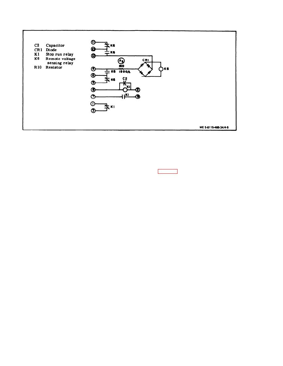
Figure 4-5.
Control Cubicle Relay Assembly, Schematic Diagram
(a) Tag and disconnect electrical leads to
terminal board,
10 and 5 and 6 and 11. There shall & no sign of con -
tinuity.
(b) Remove nut and captive washer as-
semblies (3, figure 4-3) and screw (4) to remove ter-
(c) If relay (K6) fails to function proper-
ly, proceed as follows:
minal board (5).
1.
(c) Remove screws (6) and jumpers (7)
Remove 120 Vac power.
only if inspection indicates replacement is necessary.
2.
Remove resin from back of relay
(K6).
(2) Cleaning, Inspection, and Repair.
3. Apply 120 Vac power across ter-
(a) Clean terminal board with a clean,
minals 4 and 12 and check voltage across relay (K6)
lint-free cloth lightly moistened with an approved
solvent.
coil. Voltage shall be 18 to 24 Vdc.
4. If voltage is not as specified, re-
(b) Visually inspect terminal board for
move 120 Vac and check resistance across resistor
cracks, lawns, and corrosion. Check insulating
(R1O). Resistance shall be 1500 10 ohms. If resis-
material for cracks, breaks, and other damage.
tance is not as specified, replace resistor.
5. If resistance is as specified, recti-
for continuity.
fier (CR1) is defective and must be replaced.
(d) Check all threads for crossing, stripp-
(d) Connect a 24 Vdc source across ter -
ing, and peening.
minals 8 and 2 and check for continuity across ter-
(e) Replace any damaged or defective
minals 7 and 9 and for open circuit across terminals
1 and 3. Replace relay (Kl) if continuity is not as
parts.
specified.
(3) Installation. Install control cubicle ter-
(6) Installation. Install control cubicle relay
minal board in reverse order of removal procedures.
in reverse order of removal procedures.
e. Control Cubicle Terminal Board.
(1) Removal.
f. Control Cubicle Wiring Harness.
4-6


