P-9-TM-457-35
T.O. 35C2-3-442-2
TM-07464A-35 TM 5-6115-457-34
CHAPTER 12
ELECTRIC WINTERIZATION KIT REPAIR INSTRUCTIONS
Section I. CONTROL BOX
12-1.
GENERAL.
The control box contains the oper-
ating controls of the electric winterizati on
kit. Incorporated in the box are the on-off
switch, fuse, step down transformer, full
wave diode rectifier, and heater indicator.
The switch turns kit components on or off
and the fuse protect kit components from
excessive current. The step down trans-
former converts input voltage from external
power supply to 33 VAC which in turn is
converted to approximately 24 VDC by the
full wave diode rectifier for coolant pump
operation. The indicator illuminates
whenever the kit is in operation.
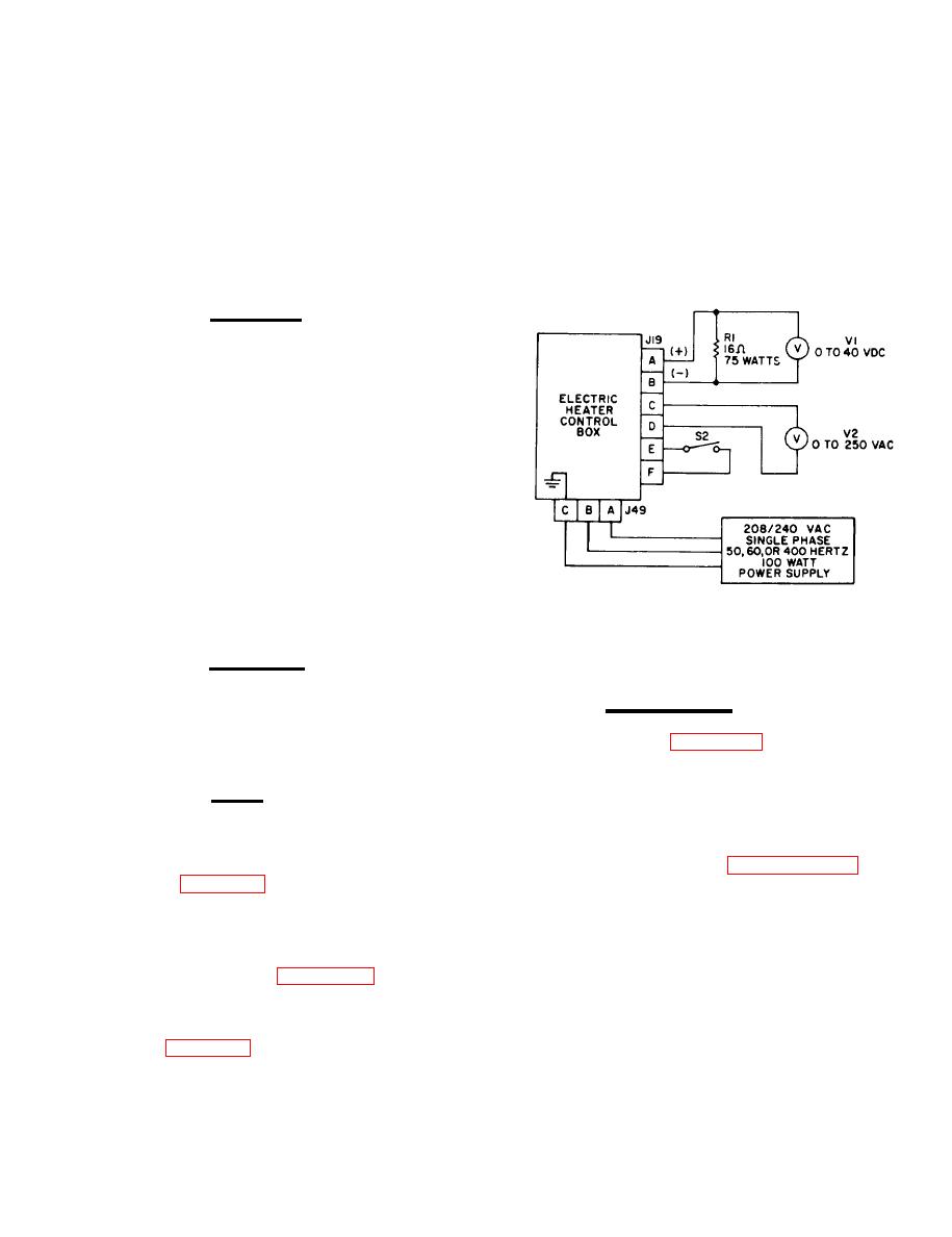
Figure 12-1. Electric winterization kit
control box, test setup
12-2.
REMOVAL.
Refer to Operator and Organiza-
12-4.
DISASSEMBLY .
tional Maintenance Manual and remove the
control box.
Refer to figure 12-2 and disassem-
ble electric winterization kit control box in
the order of index numbers assigned. Pay
1.2-3.
TEST.
particular attention to the following:
NOTE
a. Prior to control box disassembly,
test box as specified in paragraph 12-3 and
then disassemble control box only to the
terization kit schematic.
extent necessary to accomplish repair.
b. Remove cover (2). Tag and discon-
a. Connect control box to test equipment
nect harness wires from components and
as illustrated in figure 12-1.
remove harnesses (3 and 9).
c. Tag diodes (11) with location and
b. Perform test procedures as specified
polarity and remove diodes from terminal
in table 12-1.
strip by removing terminal strip screws.
12-1


