P-9-TM-457-35
T.O. 35C2-3-442-2
TM-07464A-35
TM 5-6115-457-34
c. Spin rotor by hand and check freedom
of rotation.
d. Tighten pulley nut (40) from 35 to
50 foot pounds torque.
8-19.
TEST AND ADJUSTMENT.
a. Voltage Regulator Setting Test.
1. Equipment required
(a) Variable speed drive (2000
to 3000 RPM).
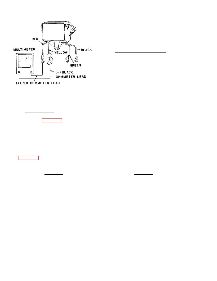
Figure 8-3. Voltage regulator
(b) Resistor (1/4 ohm 500 watt).
excitation circuit test
(c) DC voltmeter (0 to 50 volt
scale).
8-18.
REASSEMBLY.
(d) Two 12 volt batteries.
Refer to figure 8-2 and reassemble
alternator in the reverse order of index
(e) Jumper 12 inches long, No.
numbers assigned. Pay particular atten-
8 wire with two alligator clips.
tion to the following:
(f) Mating plug for alternator
NOTE
receptacle, to be wired as shown in figure
8-4.
Refer to schematic wiring diagram
2. Connect circuit as shown in fig-
leads.
ure 8-5.
CAUTION
CAUTION
To prevent overheating and possible
Alternator must be driven in direc-
tion of arrow on rear cover (15, fig-
damage to rectifier (37 and 38) diodes
ure 8-2).
when soldering, grasp diode connec-
tion terminal with long nose pliers
3. Connect alternator to variable
speed drive by means of a suitable belt and
a. When installing rear and front bear-
pulley combination.
ings (47 and 49) on shaft, use hollow sleeve
4. Run alternator up to a speed be-
the same diameter of inner races and press
tween 2000 to 3000 RPM. Connect jumper
bearings on rotor assembly shaft (51). Install
wire across 1/4 ohm resistor. Run alter-
front bearing retainer (48, VIEW c).
nator under these conditions for a warm up
b. Tighten through bolts (31) evenly.
period of at least 10 minutes.
8-10


