T.O. 35C2-3-442-2
P-9-TM-457-35
TM-07464A-35
TM 5-6115-457-34
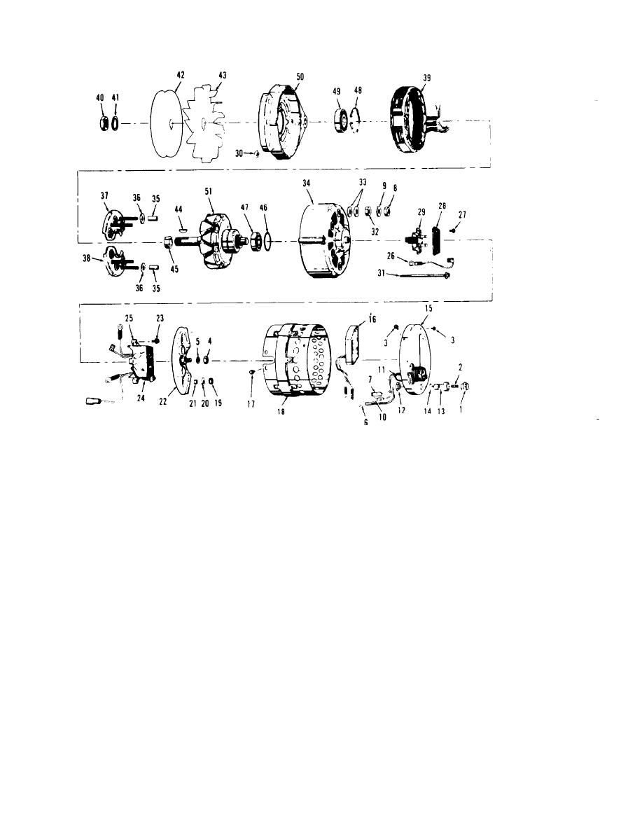
Figure 8-2. Alternator assembly, exploded view (sheet 1 of 2)
36. Washer (4)
19.
Nut (2)
1.
Cap
37. Rectifier diode
Washer (2)
20.
2.
Fuse (40 amp)
assembly
21.
Sleeve (2)
Screw (5)
3.
(positive)
22.
Isolation diode
Nut
4.
38. Rectifier diode
assembly
Washer
5.
assembly
23.
Screw (3)
6.
Connector (red)
(negative)
24.
Voltage
7.
Connector (yellow)
39. Stator assembly
adjust
Nut (2)
8.
40. Nut
rheostat
Washer (2)
9.
41. Lock washer
25.
Voltage regulator
Connector (black)
10.
42. Pulley
26.
Cable
11.
Connector (black)
43. Fan
27.
Screw (2)
Nut
12.
44. Key
28.
Cover
Receptacle
13.
45. Spacer
29.
Brush assembly
14.
Gasket
46. Retaining ring
Nut (4)
30.
15.
Cover and connector
47. Rear bearing
31.
Bolt (4)
assembly
48. Retaining ring
Nut (4)
32.
16. Circuit protector
49. Front bearing
Washer (8)
33.
17. Screw (8)
50. Front bearing
34.
Rear housing
18. Housing shield
51. Rotor assembly
35.
Sleeve (4)
assembly
8-8


