TM 5-6115-400-35
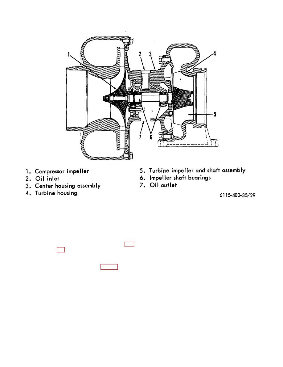
Figure 29. Turbocharger - sectional view.
(3) Remove the compressor and turbine
Note.
housings. (Refer to para. d).
For accurate indication, dial indicator
(4) Check turbine shaft radial movement as
stem end must be on same center
follows:
line as plunger of the dial indicator
adapter.
(a) Clamp
the
center
housing
compressor flange in a vise (fig.
(e) Push rotating assembly toward
indicator contact point and record
the amount of movement.
(b) Using two 3/8 inch X 1 1/8 inch
capscrews, attach dial indicator
(f) Pull the rotating assembly away
adapter, Tool F, (2, fig. 30) to the
from indicator contact point and
center housing oil drain with plunger
again record the amount of
of Tool F, resting on the impeller
movement.
shaft.
(g) The difference between the two'
(c) Attach a magnetic or clamp type
measurements is the total impeller
dial indicator to the dial indicator
movement and should be .005 inch
adapter base.
to .008 inch. Repeat this procedure
several times before accepting a
(d) Position contact point of dial
final reading.
indicator on plunge of the adapter.
63


