
TM 5-6115-400-12
h. Turn
each
adjusting
screw
downward
(clockwise) as necessary to increase clearance between
rocker arm and valve bridge. The clearance (lash) is
properly set when a feeler gage (.015" for intake valves,
.020" for exhaust) passes, with a slight drag, between
the rocker arm and valve bridge.
i. Hold adjusting screw stationary and tighten
locknut. Recheck the clearance to make certain it did
not change.
j. Adjust valves for other cylinders in firing order
sequence.
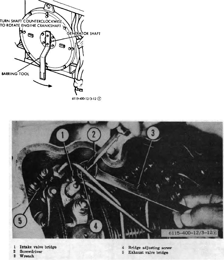
Figure 3-12 (1). Adjusting valve bridge.
Figure 3-12 (2). Continued.
3-20