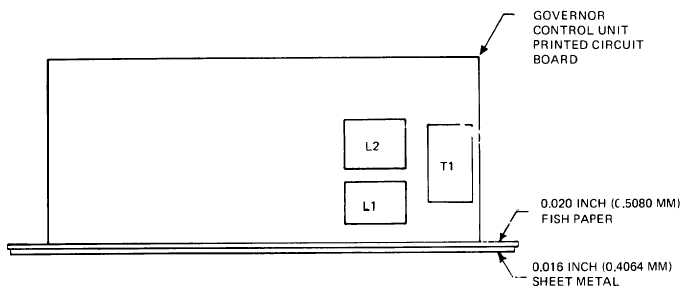
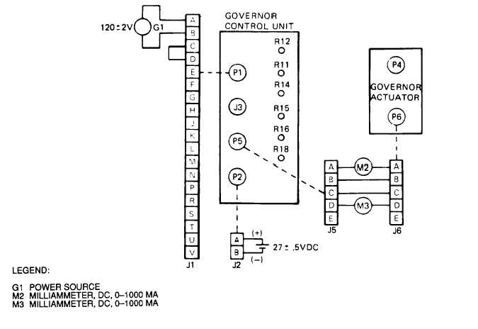
• Home
  • Download PDF
  • Order CD-ROM
  • Order in Print
Figure 3-75. 400 Hz Electro-Hydraulic Governor Control Unit Schematic Diagram, Drawing No. 69-812 (Sheet 2 of 2)
Figure  3-78.  Electro-Hydraulic  Governor  Control  Unit  Frequency  Sensing  Test  Circuit

TM-9-6115-464-34 Generator Set Diesel Engine Driven Tactical Skid Mtd 15 Kw 3 Phase 4 Wire 120/208 and 240/416 Volts Manual
Page Navigation
  206    207    208    209    210  211  212    213    214    215    216  
ARMY   TM   9-6115-464-34 AIR  FORCE  TO  35C2-3-445-2 NAVY  NAVFAC  P-8-624-34 Figure 3–76. Positioning of Unpotted Electro-Hydraulic Governor Control Unit During Testing Figure 3-77. Electro-Hydraulic Governor Control Unit Magnetic Amplifier Bias Test Circuit 3-177


Western Governors University

Privacy Statement
Press Release
Contact

© Copyright Integrated Publishing, Inc.. All Rights Reserved. Design by Strategico.